
Positioning device for welding robot and working system of welding robot

A welding robot and rectifier circuit technology, applied in welding equipment, auxiliary devices, auxiliary welding equipment, etc., can solve problems such as difficulty in meeting thick plate welding, robot position deviation, ineffective breakdown, etc., and improve fast response capabilities. , precise positioning, reducing the effect of delay

Active Publication Date: 2019-03-29
SHANGHAI STEP ELECTRIC +1
View PDF8 Cites 0 Cited by
  • Summary
  • Abstract
  • Description
  • Claims
  • Application Information

AI Technical Summary

Problems solved by technology

When the welding robot uses the matching welding machine power supply to perform contact positioning of the workpiece, the positioning voltage used is generally about 50V, which cannot effectively break down the workpiece with insulating layers such as paint, rust, and oil on the surface, so it cannot be effectively contact positioning of the workpiece
Even when searching for a workpiece without a similar insulating layer on the surface, due to the response speed of the detection circuit inside the welding power source and the delay of the communication bus with the robot, when the robot receives the signal of completion of positioning, the robot’s The position has also shifted greatly, making it difficult to meet the requirements of high-precision medium-thick plate welding

Method used


Image

  • Positioning device for welding robot and working system of welding robot
  • Positioning device for welding robot and working system of welding robot
  • Positioning device for welding robot and working system of welding robot

Examples


Embodiment Construction

[0017] The present invention will be described in detail below in conjunction with the accompanying drawings and specific embodiments.

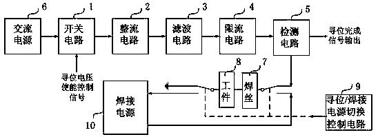
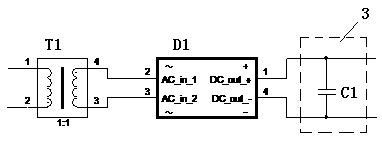
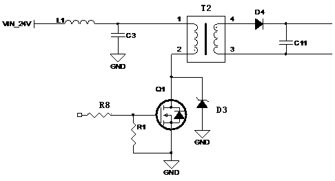
[0018] figure 1 A functional block diagram of a positioning device for a welding robot according to an embodiment of the present invention is shown. see figure 1 , according to an embodiment of the present invention, a positioning device for a welding robot includes a switch circuit 1 , a rectifier circuit 2 , a filter circuit 3 , a current limiting circuit 4 and a detection circuit 5 .

[0019] The input terminal of the switch circuit 1 is used to connect the AC power supply 6 , the output terminal of the switch circuit 1 is connected to the input terminal of the rectifier circuit 2 ; the switch circuit 1 is used to control the AC power supply 6 to be turned on or off. In this embodiment, the switch circuit is a relay, which can be controlled by an externally input seek voltage enabling signal DI. When the relay receives the enabling sign...


PUM


Abstract

The invention discloses a locating device for a welding robot. The locating device comprises a switching circuit, a rectifier circuit, a filter circuit, a current-limiting circuit and a detection circuit; the input end of the switching circuit is used for being connected with an alternating-current power supply; the output end of the switching circuit is connected with the input end of the rectifier circuit; the output end of the rectifier circuit is connected with the input end of the filter circuit and is used for converting input alternating current to direct current with the voltage being above 300V; the output end of the filter circuit is connected with the input end of the current-limiting circuit; the output end of the current-limiting circuit is connected with the input end of the detection circuit; the detection circuit is composed of a trigger element arranged on a primary side and a triggered element arranged on a secondary side; one end of the trigger element is connected with the output end of the current-limiting circuit; and the triggered element is triggered when a current flows through the trigger element and outputs a locating finishing signal. The invention also discloses a welding robot working system. The locating device can carry out safe and accurate contact type location on a workpiece with an insulation layer on the surface.

Description

technical field [0001] The invention relates to a positioning device for a welding robot and a working system of the welding robot. Background technique [0002] During the working process of the welding robot, it is often necessary to use the contact positioning method to determine the position of the welding seam. When the welding robot uses the matching welding machine power supply to perform contact positioning of the workpiece, the positioning voltage used is generally about 50V, which cannot effectively break down the workpiece with insulating layers such as paint, rust, and oil on the surface, so it cannot be effectively The contact positioning of the workpiece can be carried out. Even when searching for a workpiece without a similar insulating layer on the surface, due to the response speed of the detection circuit inside the welding power source and the delay of the communication bus with the robot, when the robot receives the signal of completion of positioning, t...

Claims


Application Information

Patent Timeline
Patent Type & Authority Patents(China)
IPC IPC(8): B23K37/00
CPCB23K37/00
Inventor 陈魁李鹏徐凯肖立佳
Owner SHANGHAI STEP ELECTRIC
Learn More