Injection molding mold opening and ejection mechanism

A technology of ejecting mechanism and ejecting block, which is applied in the direction of non-rotational vibration suppression, etc., can solve the problems of long injection molding cycle, high product defect rate, damaged barb or ball head structure, etc., so as to reduce the mold development cost and shorten the Product production cycle, good shock absorption effect

Inactive Publication Date: 2017-04-26
TIANJIN DONGMING ELECTRONICS IND
View PDF6 Cites 2 Cited by
  • Summary
  • Abstract
  • Description
  • Claims
  • Application Information

AI Technical Summary

Problems solved by technology

[0002] At present, injection mold is a kind of mold widely used in the plastic industry. It is mainly composed of pouring system, guiding system, forming system, cooling system and ejection mechanism. , both need to use male mold inserts and thimbles. The ball head structure or barb structure is formed by thimbles. After the injection molding is completed, the product needs to be separated from the mold. The existing technology requires two ejections, respectively. The plate, secondary ejector plate and thimble are completed, the first ejection: the injection molded product is ejected together with the secondary ejector plate, the second ejection is performed, the secondary ejector plate does not move, and the primary ejector plate and thimble move , the end of the thimble is forced to be pulled out. This process often damages the structure of the barb or the ball head, resulting in a high rate of defective products. Since the mold needs to be ejected twice, the use of the general ejection mechanism will make the mold structure very difficult. Complicated, which brings troubles in mold processing, assembly and post-maintenance, resulting in long injection molding cycle, low production safety factor, low production efficiency, and the existing injection mold opening and ejection mechanism has a large vibration amplitude during the working process and is easy to Defects that lead to damage to the injection mold opening and ejection mechanism due to vibration

Method used


Image

  • Injection molding mold opening and ejection mechanism

Examples


Embodiment Construction

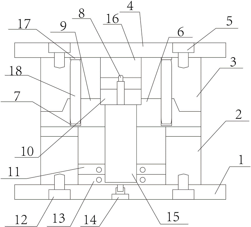
[0023] The technical solutions of the present invention will be clearly and completely described below in conjunction with the accompanying drawings. Apparently, the described embodiments are some of the embodiments of the present invention, but not all of them. Based on the embodiments of the present invention, all other embodiments obtained by persons of ordinary skill in the art without making creative efforts belong to the protection scope of the present invention.

[0024] In the description of the present invention, it should be noted that the terms "center", "upper", "lower", "left", "right", "vertical", "horizontal", "inner", "outer" etc. The indicated orientation or positional relationship is based on the orientation or positional relationship shown in the drawings, and is only for the convenience of describing the present invention and simplifying the description, rather than indicating or implying that the referred device or element must have a specific orientation, ...


PUM

PropertyMeasurementUnit
Diameteraaaaaaaaaa

Abstract

The invention aims to provide an injection molding mold opening and ejection mechanism. The mechanism comprises a male mold plate base, a male mold plate, a female mold plate, a female mold plate base, first coupling screws, a right slide block, an ejection block, a left slide block, a pushing block panel, an upper ejector plate, second coupling screws, a lower ejector plate, a pushing block, a female mold core, a guide column and a guide hole. The mechanism is characterized in that the male mold plate is arranged on the male mold plate base; the second coupling screws are arranged between the male mold plate and the male mold plate base; the male mold plate and the male mold plate base are mutually connected through the second coupling screws; a connecting base is arranged on the male mold plate base; and the connecting base and the male mold plate base are fixedly connected with each other. According to the injection molding mold opening and ejection mechanism, a spring shock absorber is arranged and can have a good shock absorbing effect on shock produced during working of the injection molding mold opening and ejection mechanism, and the situation that the injection molding mold opening and ejection mechanism receives vibration and is damaged easily due to the fact that the vibration amplitude of the injection molding mold opening and ejection mechanism in the working process is large is prevented.

Description

technical field [0001] The invention relates to the technical field of injection molds, in particular to an injection mold opening and ejection mechanism. Background technique [0002] At present, injection mold is a kind of mold widely used in the plastic industry. It is mainly composed of pouring system, guiding system, forming system, cooling system and ejection mechanism. , both need to use male mold inserts and thimbles. The ball head structure or barb structure is formed by thimbles. After the injection molding is completed, the product needs to be separated from the mold. The existing technology requires two ejections, respectively. The plate, secondary ejector plate and thimble are completed, the first ejection: the injection molded product is ejected together with the secondary ejector plate, the second ejection is performed, the secondary ejector plate does not move, and the primary ejector plate and thimble move , the end of the thimble is forced to be pulled out...

Claims


Application Information

Patent Timeline
IPC IPC(8): B29C45/40F16F15/04
CPCB29C45/4005F16F15/04
Inventor 赵志文李伟玉杨宁
Owner TIANJIN DONGMING ELECTRONICS IND
Why Eureka
Try Eureka