Aircraft layout of tilt rotors/lift fan during high-speed long endurance

A technology of tilting rotor and lift fan, which is applied in the direction of aircraft, rotorcraft, vertical take-off and landing aircraft, etc. It can solve the problems of reducing the lift-drag ratio of the whole machine and the weight of the structure, and achieves increased aspect ratio and high cruise lift. The drag ratio and the stiffness of the wing structure require a small effect

Active Publication Date: 2017-04-26
BEIHANG UNIV
View PDF6 Cites 20 Cited by
  • Summary
  • Abstract
  • Description
  • Claims
  • Application Information

AI Technical Summary

Problems solved by technology

If the vertical take-off and landing and cruising mode propulsion is achieved by using the tilting rotor method, two rotors need to be arranged on the wings on both sides, and there must be a large distance from the fuselage. Considering that the internal drive

Method used


Image

  • Aircraft layout of tilt rotors/lift fan during high-speed long endurance
  • Aircraft layout of tilt rotors/lift fan during high-speed long endurance
  • Aircraft layout of tilt rotors/lift fan during high-speed long endurance

Examples


Embodiment Construction

[0033] The present invention will be described in further detail below in conjunction with the accompanying drawings.

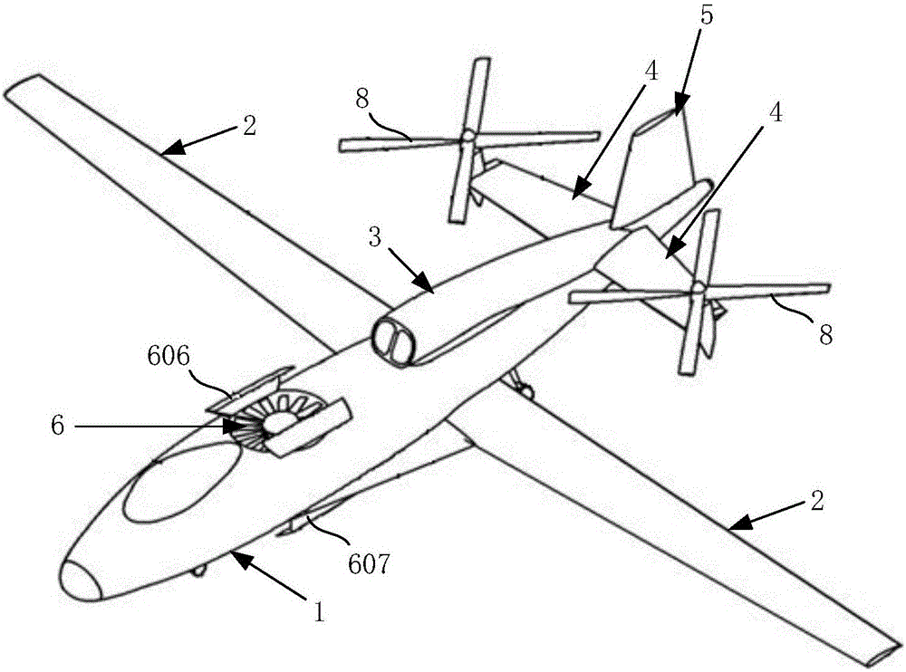
[0034] The layout of the tilt rotor / lift fan high-speed and long-endurance aircraft of the present invention is as follows: figure 1 shown. Wherein, the aircraft has the wings 2 symmetrically arranged on both sides of the fuselage 1, the engine compartment 3 designed in the middle of the fuselage 1, the horizontal tail 4 symmetrically arranged on both sides of the tail of the fuselage 1, and the vertical tail 5 arranged vertically at the tail of the fuselage 1. . An aircraft engine is installed in the above-mentioned nacelle 3 .

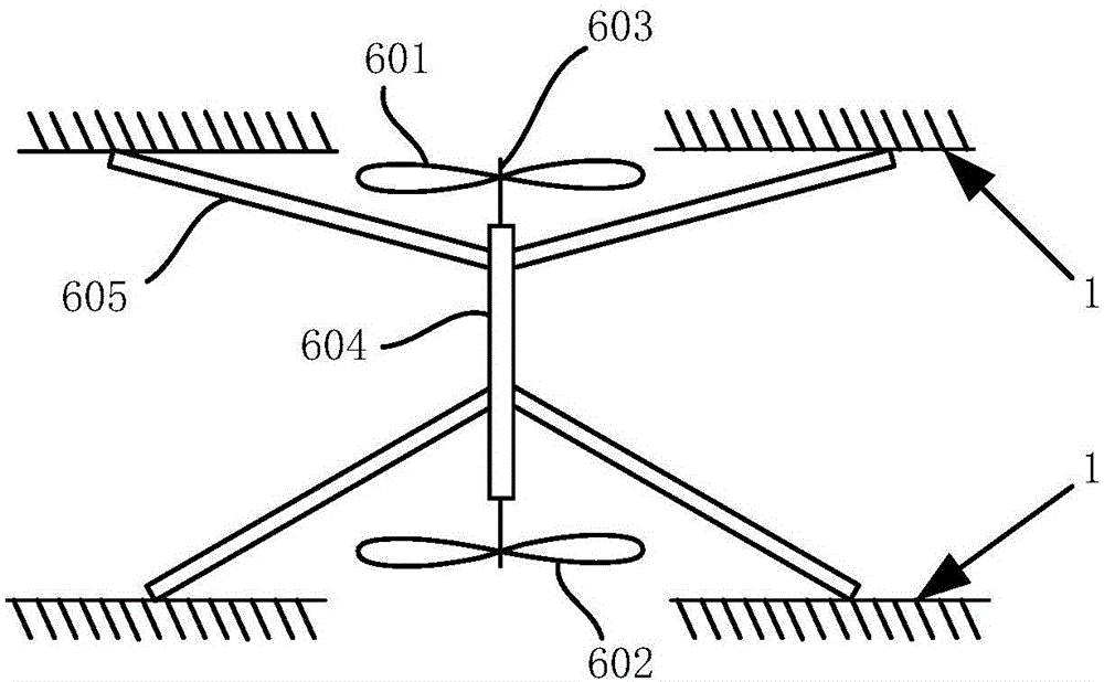
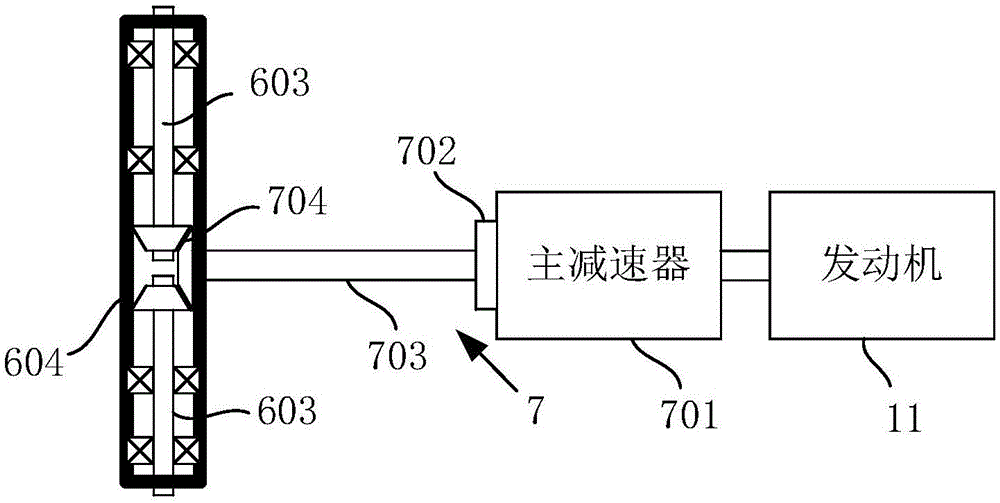
[0035] A lift fan 6 is installed in the fuselage 1 front of the aircraft, the lift fan 6 is a coaxial anti-propeller ducted fan, with an upper fan 601 and a lower fan 602, and the counter torque of itself is balanced, as figure 2 , image 3 shown. The upper fan 601 and the lower fan 602 are respectively located at the upper ai...


PUM


Abstract

The invention discloses an aircraft layout of tilt rotors/a lift fan during high-speed long endurance. The coaxial propeller reversing duct lift fan is mounted at the front part of an aircraft body; the tilt rotors are mounted at the horizontal tail end part of the rear part of the aircraft body in a bilaterally symmetric way; and in the axial direction, the tilt rotors are provided with rotational degrees of freedom within a plane perpendicular to a horizontal tail. The lift fan and the tilt rotors are provided with power by an engine in an aircraft to realize coaxial propeller reversing rotation of the lift fan and tilting of the tilt rotors within a range of 0-(+90) degrees. According to the aircraft layout of the tilt rotors/the lift fan during high-speed long endurance, the duration performance of the aircraft in a fixed wing mode can be effectively improved and the complexity of a control system can be reduced.

Description

technical field [0001] The invention belongs to the field of overall layout design of a high-speed rotorcraft, and in particular relates to the overall layout of a high-speed rotorcraft. Background technique [0002] High-speed rotorcraft is an aircraft that combines the characteristics of vertical take-off and landing of rotorcraft and the characteristics of high-speed and long-distance fixed-wing. It plays an irreplaceable important role and has a very broad application prospect. Since the invention of rotorcraft such as helicopters, it has played a huge role in the field of military and civil aviation. Because the rotor is used to provide lift, it has excellent hovering and low-speed performance, which is its advantage compared with fixed-wing aircraft. Providing lift and overcoming forward flight resistance also limits the improvement of its flight speed. It is difficult to achieve the higher speed and longer range that fixed-wing aircraft can achieve, which is not cond...

Claims


Application Information

Patent Timeline
IPC IPC(8): B64C27/28B64C27/82B64C29/02
CPCB64C27/28B64C27/82B64C29/02B64C2027/8236
Inventor 万志强蒋崇文高璞严德
Owner BEIHANG UNIV
Why Eureka
Try Eureka