
Yarn conveying device and method for electromagnetic driving circular knitting machine

An electromagnetic drive, circular weft machine technology, applied in weft knitting, textiles, papermaking, knitting, etc., can solve the problems of unable to change the position, unable to hook the yarn, and the knitting needle cannot rotate with the needle cylinder, etc., to achieve excellent quality , to ensure the effect of continuity and stability

Active Publication Date: 2017-04-26
WUHAN TEXTILE UNIV
View PDF9 Cites 6 Cited by
  • Summary
  • Abstract
  • Description
  • Claims
  • Application Information

AI Technical Summary

Problems solved by technology

[0004] The up and down motion of the knitting needle of the electromagnetic drive circular weft machine is driven by electromagnetic force. Due to the characteristics of the electromagnetic device, its position cannot be changed, so that the knitting needle cannot rotate with the needle cylinder. The yarn feeding device in the prior art is fixed on the circular weft machine. It is on a circular track, so the yarn feeding device is fixed, resulting in no relative movement between the knitting needle and the yarn during the knitting process, so that the yarn cannot be hooked and the knitting action is completed

Method used


Image

  • Yarn conveying device and method for electromagnetic driving circular knitting machine
  • Yarn conveying device and method for electromagnetic driving circular knitting machine

Examples


Embodiment Construction

[0033] In order to make the object, technical solution and advantages of the present invention more clear, the present invention will be further described in detail below in conjunction with the examples. It should be understood that the specific embodiments described here are only used to explain the present invention, not to limit the present invention.

[0034] The application principle of the present invention will be described in detail below in conjunction with the accompanying drawings.

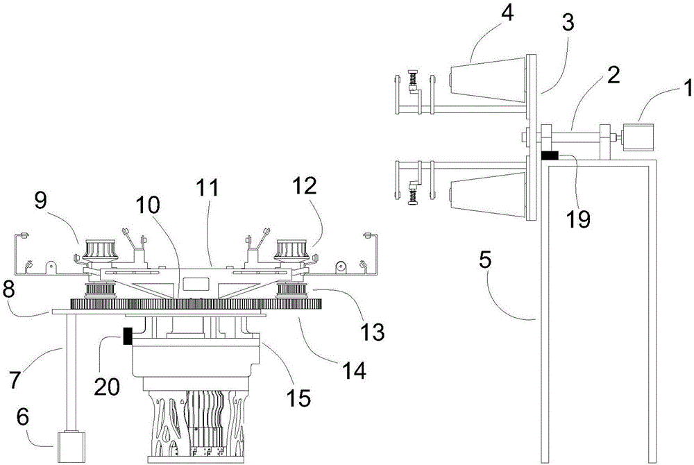
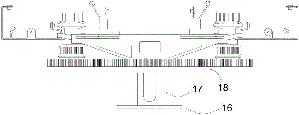
[0035] The yarn feeding method of the electromagnetically driven circular weft machine provided by the embodiment of the present invention: the yarn is pulled out from the yarn storage drum 4 by the yarn feeding wheel of the yarn feeder 9, wherein the yarn feeder 9 and the yarn storage drum 4 are each driven by a motor It is driven to rotate around the central axis to ensure that the yarns do not tangle with each other when they move in the space coordinates. The yarn delivery wheel 12...


PUM


Abstract

The invention belongs to the technical field of spinning equipment and discloses a yarn conveying method for an electromagnetic driving circular knitting machine. A yarn conveying device comprises a yarn storage drum, a yarn conveyor, a driving mechanism, a detection element and a controller, wherein the yarn storage drum is used for storing the yarns; the yarn conveyor is used for reeling the yarn; the driving mechanism is capable of realizing the stepless regulation of the yarn conveying speed; the detection element is arranged on an end face of the circular knitting machine and a yarn storage drum fixing plate; the controller is used for analyzing a detection signal and regulating the rotating speed of a yarn storage drum motor; according to the yarn conveying method for regulating the yarn conveying speed in real time by utilizing the driving mechanism, the yarn conveying volume and the yarn consumption of the fabric can be balanced; the yarn storage drum and the yarn conveyor are separately arranged and are in the working manner of independently moving, so that the knotting between the yarns moving in a space coordinate can be effectively avoided; the yarn conveyor is indirectly fixed on a cam of the circular knitting machine and an independent driving mechanism is equipped, so that the synchronous rotation of the yarn conveyor and the cam can be guaranteed, the stepless regulation of the yarn conveying speed can be realized, the yarn conveying process is continuous and the yarn-breaking automatic stopping phenomenon can be effectively avoided.

Description

technical field [0001] The invention belongs to the technical field of spinning equipment, and in particular relates to a yarn feeding device and method for an electromagnetically driven circular weft machine. Background technique [0002] In the prior art, the yarn is drawn out from the fixed yarn storage tube, and the yarn is conveyed by the fixed yarn feeder through the stationary yarn guide nozzle, thereby entering the knitting area, and the knitting needle rotates with the needle cylinder and is pushed up and down by the triangle, thereby Pick up the yarn and weave. [0003] In summary, the problems in the prior art are: [0004] The up and down motion of the knitting needle of the electromagnetic drive circular weft machine is driven by electromagnetic force. Due to the characteristics of the electromagnetic device, its position cannot be changed, so that the knitting needle cannot rotate with the needle cylinder. The yarn feeding device in the prior art is fixed on t...

Claims


Application Information

Patent Timeline
Patent Type & Authority Applications(China)
IPC IPC(8): D04B15/38D04B35/10
CPCD04B15/38D04B35/10
Inventor 张弛袁博吴晓光朱里
Owner WUHAN TEXTILE UNIV
Learn More