Method for collecting natural gas from producing well

A technology for natural gas and production wells, which is applied in the field of perforation technology to solve the blocking and burial of production pipe strings of oil and gas wells, can solve problems such as cost increase, water flooding and decline of production layers, and achieve the effect of improving gas well productivity

Inactive Publication Date: 2017-04-26
撒占东
View PDF6 Cites 0 Cited by
  • Summary
  • Abstract
  • Description
  • Claims
  • Application Information

AI Technical Summary

Problems solved by technology

[0007] The invention aims at the production drop caused by gas production with casing or oil pipe operation under pressure due to clogging of the throttle valve in the gas production pipe string or wax deposition and sand burial in the gas production well section during gas production of the gas well. , water flooding in production layers, increased cost and potential safety hazards, the present invention provides a method for collecting natural gas when the gas production string of a gas well is blocked or the production layer is buried in sand

Method used


Image

  • Method for collecting natural gas from producing well
  • Method for collecting natural gas from producing well
  • Method for collecting natural gas from producing well

Examples


Embodiment 1

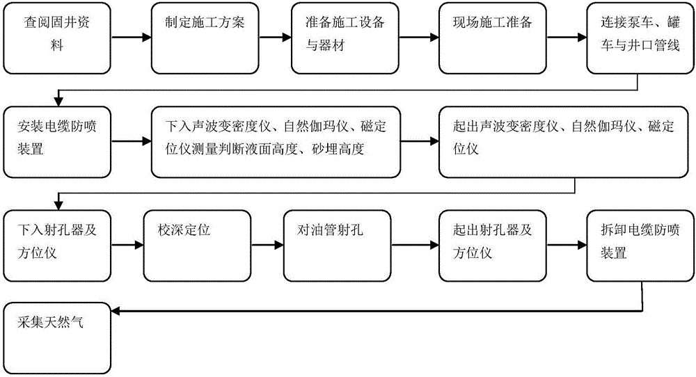
[0038] A method of collecting natural gas from a production well, comprising the steps of:

[0039] 1) Use the logging cable to lower the acoustic variable density meter, natural gamma ray meter, and magnetic positioning logging instrument into the tubing of the gas well to measure the liquid level inside the tubing and the sand burial depth outside the tubing.

[0040] 2) Determine the perforation position according to the curves measured by acoustic variable density, natural gamma ray instrument, and magnetic positioning logging tools. The principles for determining the perforation position are firstly to avoid tubing 14 and casing 9 couplings, secondly to avoid the sand-buried position, which is above the sand-buried position, and thirdly to select well sections with good cementing quality. After the above three points are satisfied at the same time, the perforation position should be as low as possible, close to the gas layer position. The well intervals with good cementi...

Embodiment 2

[0045] 1) Preparation stage:

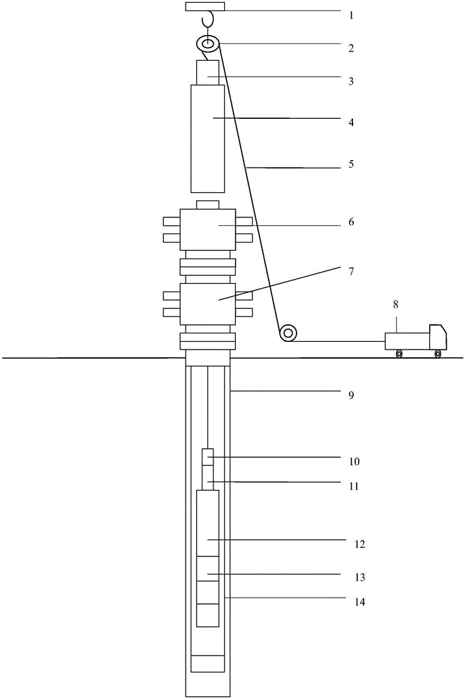
[0046] 1.1) Construction wells should be completed with Φ139.7mm casing, gas production string Φ73 tubing and throttle valve (or without throttle valve) production mode, tubing inner diameter 62mm, wall thickness 5.51mm, height of liquid column in tubing Conditions below 500m, sand buried no more than 30m, and wellhead pressure less than 35MPa.

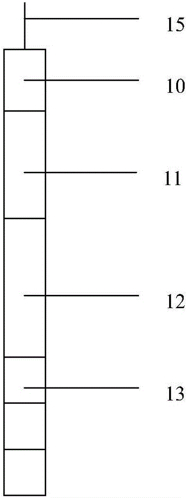
[0047] 1.2) The construction should be equipped with logging truck 8, Φ8mm single-core logging cable 5, cable protection device 10, horse bridle, Φ51mm variable density logging instrument, natural gamma meter, magnetic positioning instrument, and pressure resistance greater than 35MPa suitable for 5- 8mm cable perforation blowout preventer, cable perforation blowout preventer, perforator, weight bar 13, pump truck, water tank truck, crane and other equipment and instruments. The cable perforation blowout preventer includes a control head 3 , a blowout preventer 4 , a cable blowout preventer 6 and a dril...


PUM

PropertyMeasurementUnit
Diameteraaaaaaaaaa

Abstract

The invention relates to a method for collecting natural gas from a producing well. The method comprises the steps that (1) an acoustic variable density meter, a natural gamma ray tool and magnetic positioning logging instrument are placed into a cable perforation blowout preventer through logging cables and then transferred downwards into a gas well oil pipe for measurement; (2) the coupling position of the oil pipe and a casing pipe, the sand burying position, a well section with the good cementing quality, the natural gas reservoir position and the height of the liquid level in the oil pipe are determined according to curves measured through the acoustic variable density meter, the natural gamma ray tool and the magnetic positioning logging instrument; (3) the positions of perforation are determined; (4) perforation is conducted; and (5) the natural gas is collected through perforated holes in the oil pipe. Aiming at solving the technical problems that a natural gas collecting oil pipe is blocked, a casing pipe is forcibly used for collecting natural gas or the oil pipe is removed under pressure, and consequentially the production declines, the cost is increased and the potential safety hazards exist, the cable high-pressure closed blowout preventer is adopted for achieving operation under pressure, and the oil pipe is perforated through precise positioning and communicates with a natural gas collecting channel between the oil pipe and a stratum.

Description

technical field [0001] The invention relates to the field of natural gas exploitation in oil fields, and is a perforation technology for solving the blocking and burial of production pipe strings in oil and gas wells. Background technique [0002] At present, gas wells in most oil and gas fields in China are completed with Φ139.7mm casing, and Φ73 tubing is used for gas production. After a period of production in this gas production method, blockage of the gas production throttle valve of the tubing, wax deposition in the tubing column, or sand burial in the gas production well section and nearby areas often occur, resulting in blockage of the gas production channel of the tubing and failure to work normally, thereby affecting gas production. In this case, there are two ways to solve the problem: [0003] 1. The casing gas production method is adopted, and the casing gas production has the following defects: [0004] 1) Due to the large annular space between the casing and...

Claims


Application Information

Patent Timeline
IPC IPC(8): E21B43/25E21B43/16
CPCE21B43/25E21B43/16
Inventor 李嘉旭撒占东付起龙
Owner 撒占东
Why Eureka
Try Eureka