Environment-friendly furnace core structure
An environmentally friendly, furnace core technology, applied in the direction of combustion type, gas fuel burner, combustion method, etc., can solve the problems of poor heating effect, insufficient coal combustion, and poor versatility, and achieve convenient production, good combustion effect, Practical effect
- Summary
- Abstract
- Description
- Claims
- Application Information
AI Technical Summary
Problems solved by technology
Method used
Image

Examples
Embodiment Construction
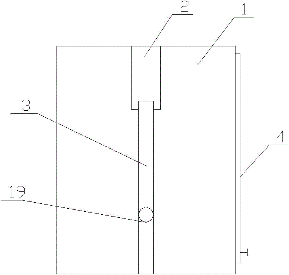
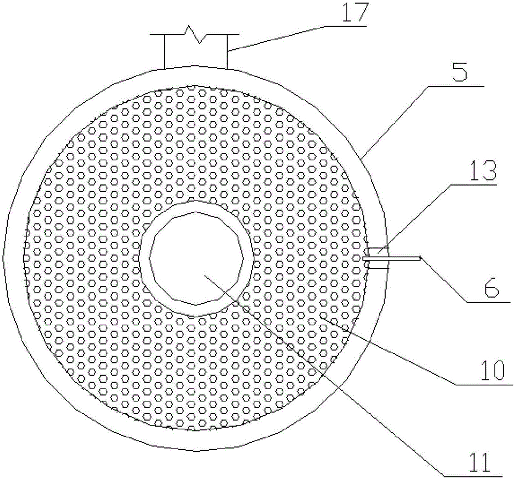
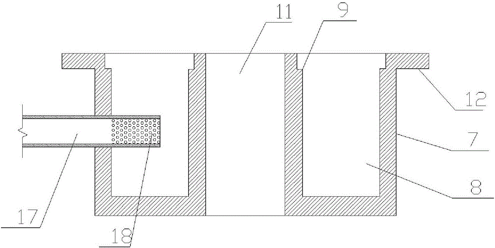
[0015] Embodiments of the present invention: a manufacturing method of an environment-friendly furnace core structure, including a furnace core body, the furnace core body is a cavity structure that penetrates up and down, a notch is provided on one side of the upper edge of the furnace core body, and a gas delivery pipe It is installed on the outside of the furnace core body and the gas outlet end of the gas delivery pipe corresponds to the position of the notch. On the other side of the furnace core body, a line connected to the power supply is provided. The furnace head of the furnace core is placed on the furnace core body through the guide of the notch. Wherein the gas inlet of the burner is communicated with the gas delivery pipe, and the igniter of the burner is communicated with the circuit.
[0016] The burner head of the furnace core includes a burner base, and an annular groove is set on the burner base so that the horizontal section of the burner base is a "back" st...
PUM
 Abstract
Description
Claims
Application Information
 - Generate Ideas
- Intellectual Property
- Life Sciences
- Materials
- Tech Scout
- Unparalleled Data Quality
- Higher Quality Content
- 60% Fewer Hallucinations
Browse by: Latest US Patents, China's latest patents, Technical Efficacy Thesaurus, Application Domain, Technology Topic, Popular Technical Reports.
© 2025 PatSnap. All rights reserved.Legal|Privacy policy|Modern Slavery Act Transparency Statement|Sitemap|About US| Contact US: help@patsnap.com