
Urea liquid level sensor test system

A testing system and sensor technology, applied in testing/calibration devices, liquid/fluid solid measurement, instruments, etc., can solve the problems of large urea level measurement error, low detection accuracy, and excessive resistance output value deviation.

Pending Publication Date: 2017-04-26
SHENZHEN HUAXIA HENGTAI ELECTRONICS
View PDF0 Cites 0 Cited by
  • Summary
  • Abstract
  • Description
  • Claims
  • Application Information

AI Technical Summary

Problems solved by technology

[0006] This detection method is inefficient and the detection accuracy is not high. Due to the different sensitivity of the magnetic field induced by each reed switch, or the failure of one of the reed switches, or the failure of a certain series resistor, it is difficult to detect such manual operation. , any failure will result in product failure
[0007] The common failure modes of urea liquid level sensors are: 1. One of the dry reed switches fails, resulting in no change in the output of a certain resistance; 2. One of the resistances fails, resulting in an excessive deviation of the output value of a certain resistance; 3. The dry reed The difference in tube sensitivity is large, which leads to too large difference in the interval of resistance change. For example, the standard is that the resistance value changes at a 20mm interval. Because of the difference in sensitivity or the welding position of the dry reed switch, some resistance values ​​correspond to 15mm intervals, and some resistance values ​​correspond to The distance between the two parts is 28mm, which will cause the measurement error of the customer's urea liquid level to increase and affect the measurement accuracy; 4. False welding of the reed switch or series resistance, false welding, etc. lead to unstable resistance value of a certain section
[0008] In the production process of urea liquid level sensor products, it is difficult to find the above-mentioned failure modes by traditional testing methods, and even if they are found, it is difficult to track down which specific component is the problem

Method used


Image

  • Urea liquid level sensor test system

Examples


Embodiment Construction

[0019] Below in conjunction with accompanying drawing, the present invention will be further described.

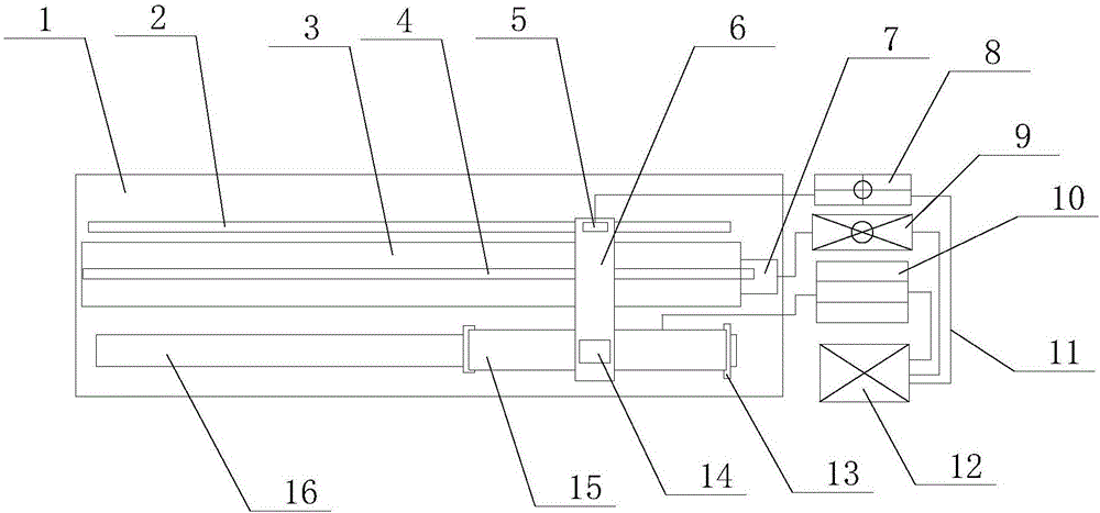
[0020] see figure 1 As shown, the technical solution adopted in this specific embodiment is: it includes a marble platform 1, a grating ruler 2, a linear guide rail 3, a guide rail screw 4, a guide rail slider 6, a stepper motor 7, a product mounting bracket 16, and a urea liquid level Sensor product 15, floating ball 14, multimeter 10; described grating ruler 2 is attached on the marble platform 1; grating ruler 2 is provided with grating ruler reading head 5; grating ruler reading head 5 is connected with grating reading module 8; The linear guide rail 3 is arranged on the marble platform 1; the linear guide rail 3 is arranged on the side of the grating ruler 2; the guide rail slider 6 is arranged on the linear guide rail 3; The terminal is connected to the stepper motor 7; the stepper motor 7 is connected to the motor control module 9; the grating ruler reading head 5 ...


PUM


Abstract

The invention discloses a urea liquid level sensor test system. The urea liquid level sensor test system includes a marble platform and a grating ruler, wherein the grating ruler fits the marble platform; a grating ruler reading head is arranged on the grating ruler; the grating ruler reading head is connected with a grating reading module; a linear guide rail is arranged on the marble platform; a guide rail sliding block is arranged on the linear guide rail; the guide rail sliding block is in rotary connection with a guide rail leading screw; an end socket of the guide rail leading screw is connected with a stepping motor; the stepping motor is connected with a motor control module; the grating ruler reading head and a floating ball are respectively fixed at two ends of the guide rail sliding block; the grating ruler, the linear guide rail and a product mounting support are parallel to each other; a urea liquid level sensor product is arranged on the product mounting support; a sensor output end of the urea liquid level sensor product is connected with a universal meter; and the grating reading module, the motor control module and the universal meter are connected with a control terminal. The urea liquid level sensor test system has the advantages of being high in detection precision of products, being high in production efficiency, reducing detection man-hour of products, and reducing the manufacturing cost of products.

Description

technical field [0001] The invention relates to the technical field of urea liquid level sensor detection, in particular to a urea liquid level sensor testing system. Background technique [0002] The urea level sensor is used to measure the urea level in the SCR system of a diesel truck. It is installed on the urea tank, and the stainless steel tube at the lower end is inserted into the urea solution. The solution is heated to prevent the urea solution from freezing at low temperatures. The pipeline with a float ball has a reed switch circuit inside to sense the different positions of the float and measure the signal of the output urea level. [0003] A long circuit board is installed in the stainless steel tube with the float, and a set of dry reed switches are welded on the circuit board to sense the position of the float. The float is encapsulated with permanent magnets, which can ensure that there are dry reed switches in different positions of the float. Being pulled ...

Claims


Application Information

Patent Timeline
IPC IPC(8): G01F25/00
CPCG01F25/22G01F25/20
Inventor 贾庆锋
Owner SHENZHEN HUAXIA HENGTAI ELECTRONICS
Learn More