Fluorescent wheel and two-color laser source

A laser light source and fluorescent wheel technology, which is applied in the field of fluorescent wheels and two-color laser light sources, can solve the problems of unfavorable laser equipment miniaturization and large light source volume, and achieve the effect of improving light processing efficiency

Active Publication Date: 2017-04-26
QINGDAO HISENSE LASER DISPLAY CO LTD
View PDF13 Cites 31 Cited by
  • Summary
  • Abstract
  • Description
  • Claims
  • Application Information

AI Technical Summary

Problems solved by technology

[0009] The invention provides a fluorescent wheel and a two-color laser light source. By setting a diffusion plate in the transmission area of ​​the fluorescent wheel, while the fluorescent wheel sequentially outputs laser light and fluorescent light, it can also diffuse the transmitted laser light to play the role of dissipating spots. The separate speckle dissipation parts are omitted, which improves the light processing efficiency of the fluorescent wheel, and also solves the technical problem that the two-color laser light source has a large volume due to the complex optical structure design, which is not conducive to the miniaturization of laser equipment.

Method used


Image

  • Fluorescent wheel and two-color laser source
  • Fluorescent wheel and two-color laser source
  • Fluorescent wheel and two-color laser source

Examples


Embodiment 1

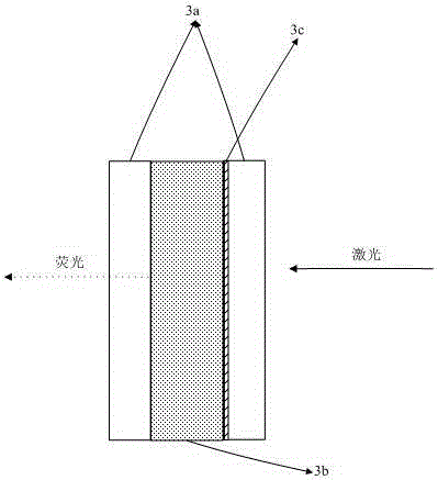
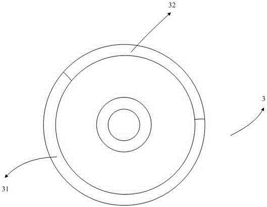
[0046] Embodiment 1 of the present invention provides a fluorescent wheel, driven by a motor to rotate, such as image 3 As shown, the fluorescent wheel 3 is disc-shaped and includes a fluorescent area 31 and a non-fluorescent area, wherein the non-fluorescent area includes a central motor shaft area and a transmissive area 32 . Among them, such as Figure 7As shown, the fluorescent area 31 includes a green fluorescent layer 311 and a coating layer 312 on the green fluorescent layer 311 . Among them, the green fluorescent layer 311 of the fluorescent area 31 is used to accept the excitation of the incident laser excitation light to generate fluorescence, and the transmissive area 32 is not provided with phosphor powder, which is used to provide an independent channel for the transmission of the laser light, so that when the laser light source rotates on the fluorescent wheel The non-fluorescent excitation time period of the laser light includes a laser excitation light source...

Embodiment 2

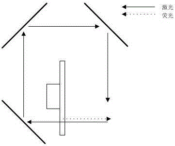
[0062] Embodiment 2 of the present invention provides a two-color laser light source, such as Figure 9 As shown, it includes a laser light source unit 1, including a blue laser and a red laser, which emit blue laser and red laser respectively; The large laser spot is focused, and the small spot reduced to a set size is incident on the fluorescent wheel 3 .

[0063] Among them, the fluorescent wheel 3 is the fluorescent wheel described in Embodiment 1, and the fluorescent wheel 3 includes a green phosphor area. Because the blue laser has a short wavelength, according to the principle of energy transition and wavelength conversion, a blue laser with a shorter wavelength is selected as the excitation. light to excite the green fluorescent powder to produce green fluorescence; wherein, the substrate in the green fluorescent powder area on the fluorescent wheel 3 is a transparent substrate, and the blue laser light-incident side of the transparent substrate is coated with a wavele...

Embodiment 3

[0080] Embodiment 3 of the present invention is a modification or improvement on the basis of Embodiment 2, and the same parts and beneficial effects as Embodiment 2 will not be repeated here.

[0081] The difference from Example 2 is that, as Figure 12 As shown, the blue laser 11 and the red laser 12 in the laser light source unit 1 in the embodiment of the present invention are arranged side by side, rather than vertically. It should be noted that the arrangement of the blue laser and the red laser does not affect the present invention. The essential purpose of the technical solution of the invention is that when the two are vertically arranged in Embodiment 1, the heat dissipation parts for the laser light source can be arranged in the right-angled space formed by the two vertically, and the lasers of the two colors are dissipated respectively, and the lasers of the two colors are arranged side by side. When arranged, the heat dissipation part needs to be arranged above or...


PUM


Abstract

The invention discloses a fluorescent wheel. A transmission area adopts a diffusion plate, so that while realizing laser transmission, diffusion can also be realized, thereby achieving a speckle removing effect, saving an extra speckle removing component and improving light processing efficiency of the fluorescent wheel. The invention also discloses a two-color laser source using the fluorescent wheel above. Output of three-primary-color light can be realized through the fluorescent wheel part, and transmitting two-color laser can be subjected to speckle removing. The fluorescent wheel and the two-color laser source are applied to the laser illumination and display field.

Description

technical field [0001] The invention relates to the field of laser lighting and display, in particular to a fluorescent wheel and a two-color laser light source. Background technique [0002] Laser is a light source with high brightness, strong directionality, and monochromatic coherent light beam. Due to its many advantages, it has been gradually used as a light source in the field of projection display technology in recent years. However, the speckle problem of pure laser light sources is serious and the cost is high. At present, laser light sources mixed with fluorescence and laser are widely used. [0003] Among them, the fluorescence is generated by coating phosphor powder on the wavelength conversion device and exciting the phosphor powder with laser light. For example, a blue laser is used to excite green and red phosphors to generate three primary colors of light. The green phosphor and the red phosphor wheel are coated on a rotating wavelength conversion device, wh...

Claims


Application Information

Patent Timeline
Patent Type & Authority Applications(China)
IPC IPC(8): G03B21/20G03B21/14
CPCG03B21/14G03B21/2033G03B21/204G03B21/208
Inventor 田有良王强刘显荣李巍
Owner QINGDAO HISENSE LASER DISPLAY CO LTD
Why Eureka
Try Eureka