A stator assembly and its manufacturing method

A component and stator technology, applied in the field of stator components and its manufacturing, can solve the problems of large individual differences in motor performance and inconvenient positioning of stator cores, etc., and achieve convenient and accurate positioning, simple structure, guaranteed sealing and anti-rust capabilities Effect

Active Publication Date: 2019-05-28
ZHONGSHAN BROAD OCEAN
View PDF4 Cites 0 Cited by
  • Summary
  • Abstract
  • Description
  • Claims
  • Application Information

AI Technical Summary

Problems solved by technology

This kind of stator assembly often has the following disadvantages: due to the inconvenient positioning of the stator core during plastic packaging or installation, there are large individual differences in the performance of the motor

Method used


Image

  • A stator assembly and its manufacturing method
  • A stator assembly and its manufacturing method
  • A stator assembly and its manufacturing method

Examples


Embodiment 1

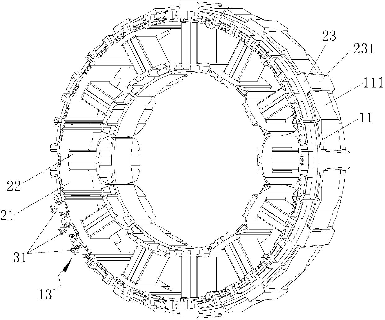
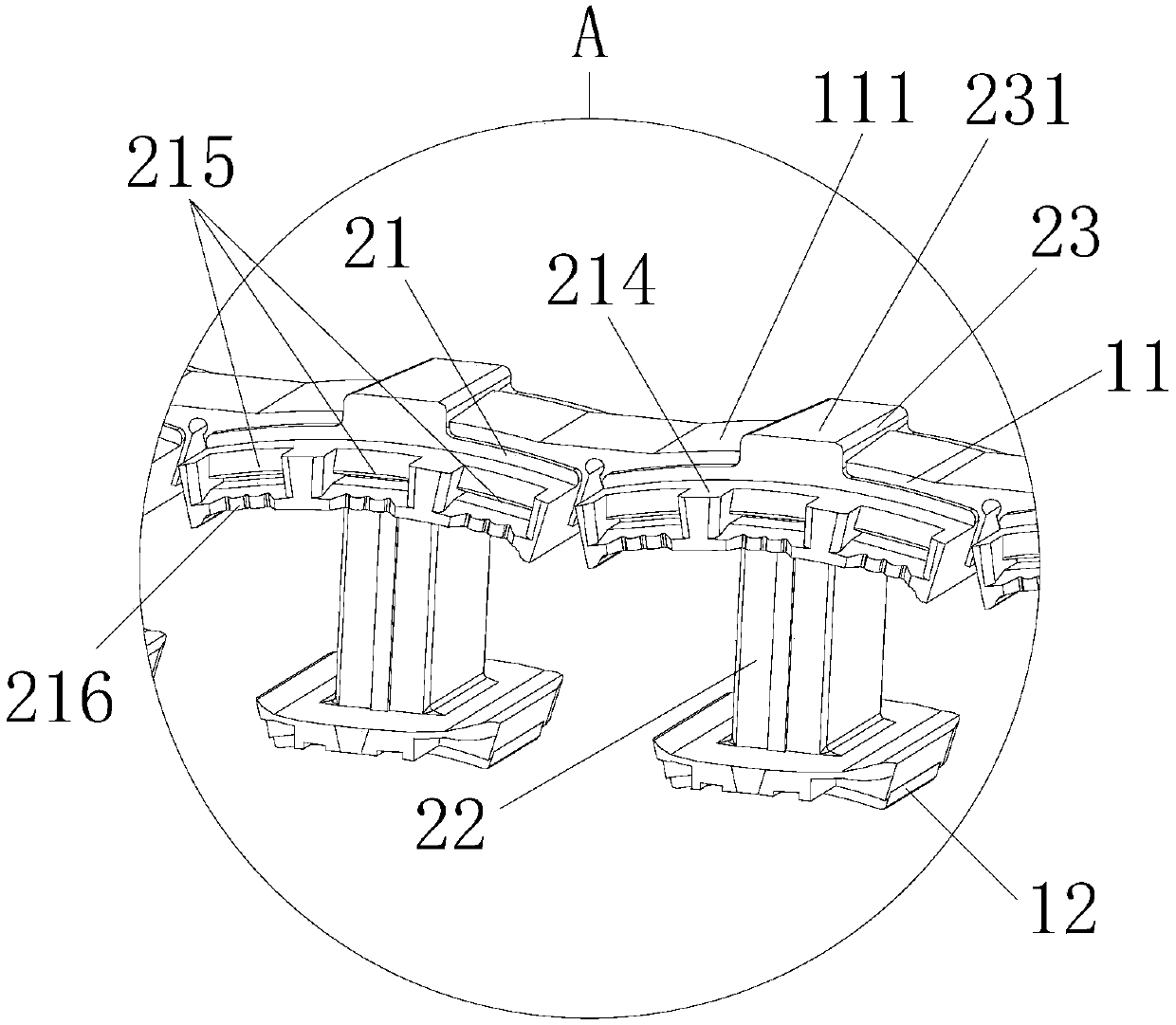
[0041] like Figure 1 to Figure 7 As shown, this embodiment provides a stator assembly, including a stator core 1, an end insulation 2 installed on the stator core 1, and a coil winding 3 wound on the end insulation 2, The stator core 1 includes a yoke 11 and several teeth 12 protruding from the inner side of the yoke 11, the end insulation 2 includes an insulating yoke 21 and an insulating tooth 22, and the insulating teeth 22 fit into Sleeved on the tooth part 12, the insulating yoke part 21 is nested on the yoke part 11, and the feature is that the end part insulation 2 also includes several positioning ribs 23, and the positioning ribs 23 protrude from the The outer surface 111 of the yoke 11 is connected to the insulating yoke 21 , and an axial inclined surface 231 is provided on the outer side of the positioning rib 23 .

[0042] The stator assembly described in this embodiment has a simple structure, the positioning ribs 23 can protect the stator core 1 , and the axial...

Embodiment 2

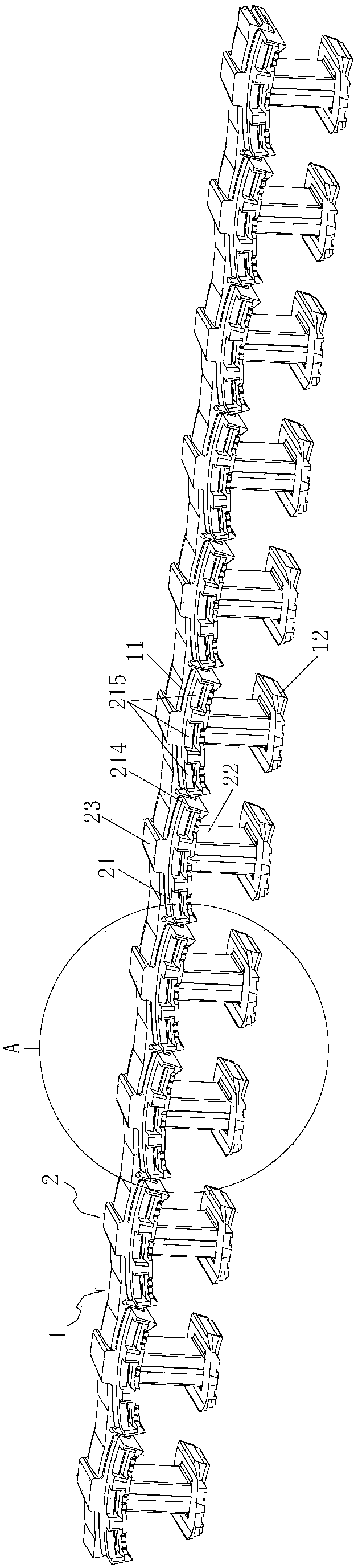
[0052] like Figure 8 to Figure 10 As shown, this embodiment provides a method for manufacturing a stator assembly, which is characterized in that it includes:

[0053] Step 1, end insulation injection molding: put the strip stator core 1 into the injection mold, and inject the end insulation 2 outside the strip stator core 1;

[0054] Step 2, winding: winding and installing the three-phase coil winding on the insulating tooth portion 22;

[0055] Step 3, wiring: connect the thread ends of the three-phase coil windings to the lug 31, select any stator core unit as the positioning unit 13, and install the three lugs 31 in the wiring groove 215 of the positioning unit 13;

[0056] Step 4, mold loading: roll the stator assembly into a circle and put it into the annular cavity 5 of the plastic sealing mold. The outer circular side wall 51 of the annular cavity 5 is provided with an axially inclined positioning surface 511, so that the teeth The bottom of 12 is attached to the inne...


PUM


Abstract

The invention discloses a stator assembly and a manufacturing method thereof. The stator assembly comprises a stator core, and a coil winding which is installed at the end part insulation of the stator core and winds the end part insulation. The stator core comprises a yoke part and tooth parts projecting from the inner side of the yoke part. The end part insulation comprises insulation yoke parts and insulation tooth parts which sleeve the tooth parts. The insulation tooth parts sleeve the tooth parts. The insulation yoke parts sleeve the yoke part. The end part insulation also comprises a plurality of positioning ribs which are raised from the outer side of the yoke part and are connected to the insulation yoke parts. The outer sides of the positioning ribs are provided with axial inclined planes. The stator assembly has the advantages of a simple structure and convenience in manufacture, the stator core can be protected by the positioning ribs, the axial inclined planes of the positioning ribs play a good positioning role in the plastic sealing or installation of the stator assembly.

Description

Technical field: [0001] The invention relates to a stator assembly and its manufacturing method. Background technique: [0002] The existing stator assembly includes a stator core, end insulation mounted on the stator core, and coil windings wound on the end insulation, the stator core includes a yoke and teeth protruding from the inside of the yoke, the The end insulation includes an insulating yoke, the insulating tooth is nested on the tooth, and an insulating yoke is nested on the yoke. This kind of stator assembly often has the following disadvantages: due to the inconvenient positioning of the stator core during plastic packaging or installation, there are large individual differences in the performance of the motor. Invention content: [0003] The purpose of the present invention is to provide a stator assembly and a manufacturing method thereof, the stator assembly is easy to locate and has consistent performance. [0004] The purpose of the present invention is ...

Claims


Application Information

Patent Timeline
Patent Type & Authority Patents(China)
IPC IPC(8): H02K1/14H02K3/38H02K15/02H02K15/00
CPCH02K1/145H02K1/146H02K3/38H02K15/0081H02K15/022
Inventor 黄洋波金建伟潘明攀胡辉
Owner ZHONGSHAN BROAD OCEAN
Why Eureka
Try Eureka