
Current detection circuit and power conversion device

A technology of power conversion device and current detection circuit, which is applied in the direction of output power conversion device, conversion of DC power input to DC power output, high-efficiency power electronic conversion, etc., to reduce the number of peripheral components, improve precision, and reduce power consumption loss effect

Pending Publication Date: 2017-04-26
CHIPONE TECH BEIJINGCO LTD
View PDF5 Cites 5 Cited by
  • Summary
  • Abstract
  • Description
  • Claims
  • Application Information

AI Technical Summary

Problems solved by technology

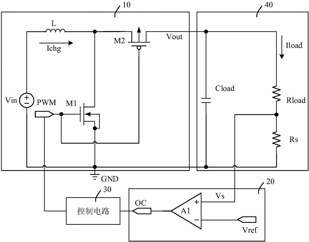
But if the input and output range of the circuit is too large, the duty cycle D may change from 10% to 90% when the circuit is fully loaded, and the peak value of the inductor current is not enough to accurately reflect the variation of the output load current Iload, so the output average load current The detection and protection circuit is extremely important

Method used


Image

  • Current detection circuit and power conversion device
  • Current detection circuit and power conversion device
  • Current detection circuit and power conversion device

Examples


Embodiment Construction

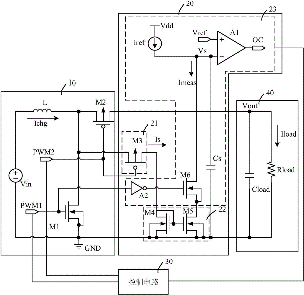
[0027] Various embodiments of the invention will be described in more detail below with reference to the accompanying drawings. In the various drawings, the same elements are denoted by the same or similar reference numerals. For the sake of clarity, various parts in the drawings have not been drawn to scale.

[0028] The invention can be embodied in various forms, some examples of which are described below.

[0029] image 3 A circuit diagram of a power conversion device provided according to an embodiment of the present invention is shown. Such as image 3 As shown, the power conversion device includes a power conversion module 10 , a current detection circuit 20 and a control circuit 30 .

[0030]Wherein, the power conversion module 10 includes an input voltage terminal Vin, an output voltage terminal Vout, a first power switch tube M1, a second power switch tube M2, and an inductor L, and the inductor L and the first power switch tube M1 It is connected in series betw...


PUM


Abstract

The present invention discloses a current detection circuit. The circuit is configured for a power conversion device, and comprises a sampling unit, a mirror image unit and a detection unit, wherein the sampling unit is configured to connect with the power conversion device and configured to obtain the sampling current signals of the power conversion device, the mirror image unit is connected with the sampling unit and the detection unit and is configured to input the sampling current signal mirror images into the detection unit, and the detection unit is configured to generate current detection signals and feed back the control power conversion device according to the sampling current signals, the standard current signals and the standard voltage signals. The current detection circuit and the power conversion device provided by the embodiment of the invention realize the over-current detection of the output average load current through detection of output load so as to improve the precision of the over-current detection circuit and effectively reduce the number of the peripheral devices of the chips, and moreover, because the detection current is far smaller than the load current of the chips, the power consumption loss of the chips brought by the over-current detection circuit is effectively reduced.

Description

technical field [0001] The invention belongs to the technical field of integrated circuits, and more specifically relates to a current detection circuit and a power conversion device. Background technique [0002] In the DC-DC switching power supply circuit, in order to protect the internal circuit of the chip, the overcurrent detection of the inductor current is performed, or the short circuit or open circuit of the input and output voltage is detected, as well as the over temperature and under voltage detection. Among them, the detection and protection circuit for load current rarely appears, and it is generally replaced by overcurrent detection for the inductor current. But if the input and output range of the circuit is too large, the duty cycle D may change from 10% to 90% when the circuit is fully loaded, and the peak value of the inductor current is not enough to accurately reflect the variation of the output load current Iload, so the output average load current The...

Claims


Application Information

Patent Timeline
IPC IPC(8): H02M3/158
CPCH02M3/158H02M1/0048H02M1/0009Y02B70/10
Inventor 金宁杨康
Owner CHIPONE TECH BEIJINGCO LTD
Learn More