

Electric driving unit, chopper circuit, DC motor and electric equipment
An electric drive, DC motor technology, applied in the direction of connection with control/drive circuits, DC motor speed/torque control, electromechanical devices, etc., can solve the problem of limited battery voltage amplitude, current sharing failure, poor current sharing effect, etc. problems, to avoid the consumption of human and financial resources and reduce the requirements of performance consistency
- Summary
- Abstract
- Description
- Claims
- Application Information
AI Technical Summary
Problems solved by technology
Method used
Image

Examples
Embodiment Construction
[0036] The specific implementation manners of the present invention will be described below in conjunction with the accompanying drawings.
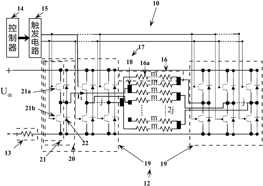
[0037] figure 1 is a schematic diagram of the circuit structure of the electric drive device in this embodiment.
[0038] The electric driving device 10 is installed in electric equipment such as electric tools, quadcopters, electric vehicles, electric boats, industrial electric forklifts, and electric military equipment, and is used to drive the electric equipment. Such as figure 1 As shown, the electric driving device 10 includes a DC motor 11 , a DC power supply, a bridge reversible chopper circuit 12 , a main magnetic pole 13 , a controller 14 and a trigger circuit 15 .
[0039] The DC motor 11 has a rated voltage and a rated current. The DC motor 11 has 2j mutually independent armature winding branches 16 , 2j×m commutator segments (not shown in the figure) and 2 sets of brush sets 17 .
[0040] The armature winding branch 16 i...
PUM
 Abstract
Description
Claims
Application Information