Illumination-intensity-adjustable no flickering visible light communication transmitting end controller

A technology of visible light communication and light intensity, applied in the field of visible light communication, can solve the problems that LED lights are easy to enter flicker mode, harmful to users, etc., and achieve reliable signal transmission, short development cycle, and good robustness.

Inactive Publication Date: 2017-04-26
SHANDONG UNIV
View PDF0 Cites 3 Cited by
  • Summary
  • Abstract
  • Description
  • Claims
  • Application Information

AI Technical Summary

Problems solved by technology

But this design has the following defects: when a long series of '0' data or '1' data is transmitted for a relatively long period of time, the LED light will easily enter the flicker mode, which is harmful to the user

Method used


Image

  • Illumination-intensity-adjustable no flickering visible light communication transmitting end controller

Examples


Embodiment 1

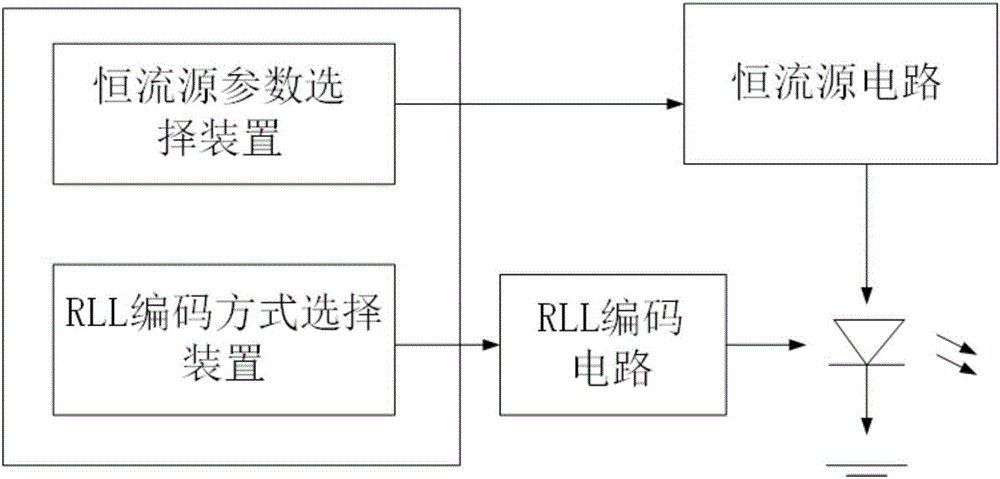
[0034] A visible light communication transmitter controller with adjustable light intensity and no flicker, including a constant current source drive circuit and a digital RLL encoding module, the constant current source drive circuit includes a constant current source parameter selection device and a constant current source circuit, The digital RLL encoding module includes an RLL encoding mode selection device and an RLL encoding circuit; the constant current source circuit performs real-time adjustment of constant current parameters under the control of the constant current source parameter selection device; the RLL encoding circuit is in the RLL Under the control of the encoding mode selection device, the encoding mode is adjusted in real time.

[0035]The digital RLL coding module codes and modulates signals through non-stop switching modes, and periodically provides 'on / off' control logic to the constant current source drive circuit within a control cycle; all signals that...

Embodiment 2

[0038] A working method of the controller as described in embodiment 1, comprising the steps of:

[0039] 1) Utilize the digital RLL encoding module to channel encode, pre-equalize and modulate the digital signal;

[0040] 2) The digital RLL encoding module periodically provides the control logic of 'on / off' to the constant current source drive circuit within a control cycle through the non-stop switching mode encoding modulated signal;

[0041] 3) The constant current source driving circuit provides a constant current source for the controlled LED lamp: when the control signal sent by the digital RLL encoding module is in the 'on' control logic state, the LED lamp is turned on by the current source On; when the control signal sent by the digital RLL encoding module is in the 'off' control logic state, the LED light is in the off state.

Embodiment 3

[0043] The working method as described in Embodiment 2, the difference is that in step 1), the digital RLL encoding module includes but not limited to Manchester encoding, differential Manchester encoding, 4B / 6B encoding and 8B / 10B encoding.


PUM


Abstract

The invention relates to an illumination-intensity-adjustable no flickering visible light communication transmitting end controller. The controller comprises a constant current source driving circuit and a digital RLL coding module, wherein the constant current source driving circuit comprises a constant current source parameter selection device and a constant current source circuit, the digital RLL coding module comprises an RLL coding mode selection device and an RLL coding circuit, and the constant current source circuit is under the control of the constant current source parameter selection device to carry out real-time constant current parameter adjustment, and the RLL coding circuit is under the control of the RLL coding mode selection device to carry out real-time coding mode adjustment. The controller is advantaged in that real-time brightness grade adjustment on LED lamps is realized through utilizing run length limited codes and the constant current source driving circuit, no system flickering phenomenon occurs, and high-speed signal transmission can be kept.

Description

technical field [0001] The invention relates to a visible light communication transmitter controller with adjustable light intensity and no flicker, and belongs to the technical field of visible light communication. Background technique [0002] Using a constant DC bias current plus a transmission signal current is a very common method in the design of the visible light communication transmitter. This type of system is realized by adding a constant DC bias current to the drive circuit, that is, keeping the LED light in a constant bright state. The digital signal is converted into an analog signal by a digital-to-analog conversion circuit, and then superimposed on the DC bias current to drive the LED lamp as a transmission signal, so the brightness adjustment change of the LED lamp is synchronized with the intensity change of the transmission signal in real time. [0003] However, the above method has the following disadvantages: [0004] A) Since the driving current change...

Claims


Application Information

Patent Timeline
IPC IPC(8): H04B10/516H04B10/116
CPCH04B10/5161H04B10/116
Inventor 周莉孙济生张文胜孙健王承祥
Owner SHANDONG UNIV
Why Eureka
Try Eureka