

Percutaneous skin-puncture traction retractor radially unfolded in visual endoscopy
A technology of radial deployment and skin traction, applied in puncture needles, puncture needles, medical science, etc., can solve the problems of increased labor intensity of medical staff, limited surgical operation space, and single function, so as to reduce local stress on the skin , Save operation time, improve operation efficiency
- Summary
- Abstract
- Description
- Claims
- Application Information
AI Technical Summary
Problems solved by technology
Method used
Image

Examples
Embodiment
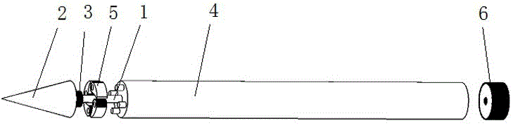
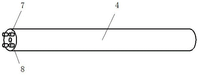
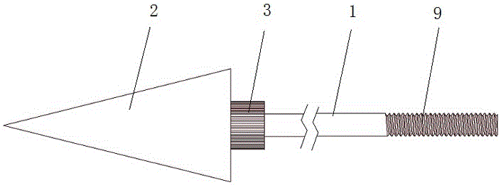
[0021] Embodiment: a percutaneous puncture skin traction hook radially deployed under a visual endoscope, such as figure 1 shown. The device includes a central core rod 1 and a sleeve 4 nested inside and outside. The front end of the central core rod protrudes from the front end of the sleeve, and is provided with a top cone 2 for piercing the skin. unanimous. Such as figure 1 As shown, four outstretched group petals 5 are evenly arranged around the central core rod between the rear side of the top cone and the front end of the sleeve, and a ring gear 3 is provided on the central core rod close to the rear surface of the top cone, as shown in Figure 4 As shown, an arc-shaped tooth surface 10 is provided on the inner side of the abduction group petals, and the ring gear and the arc-shaped tooth surface mesh with each other. Such as figure 2 As shown, four swing shafts 7 protrude forward from the front end of the sleeve, and the front end of the swing shaft abuts against t...
PUM
 Abstract
Description
Claims
Application Information