Ring cutter

A ring cutting and cutting tool technology, which is applied to cable installation devices, metal processing, electrical components, etc., can solve the problems of damaged cores, reduced production efficiency, and difficulty in determining the depth of cutting tools, so as to reduce the frequency of tool replacement and improve production. efficiency effect

Active Publication Date: 2018-07-17
MIND ELECTRONICS APPLIANCE CO LTD
View PDF4 Cites 0 Cited by
  • Summary
  • Abstract
  • Description
  • Claims
  • Application Information

AI Technical Summary

Problems solved by technology

The existing stripping tools and devices have the following disadvantages: V-shaped knife or arc blade models match the diameters of cables and pipes, and different types of blades need to be used when removing the surface layers of cables and pipes with different diameters, so the frequency of blade replacement High, resulting in reduced production efficiency; when the V-shaped knife or arc blade is applied, it relies on external force to squeeze the outer peripheral surface of the cable or pipe to cut into the surface of the cable or pipe. When the surface material of the cable or pipe is soft, the extrusion force will The lower deformation is large, so it is difficult to determine the depth of the lower knife, and when the cable and pipe material have strong toughness, a larger extrusion force is required to remove the surface layer, and it is difficult to ensure the size of the lower knife. The above two cases use too little force The purpose of peeling cannot be achieved, and the core body is damaged due to excessive force

Method used


Image

  • Ring cutter
  • Ring cutter
  • Ring cutter

Examples


Embodiment 1

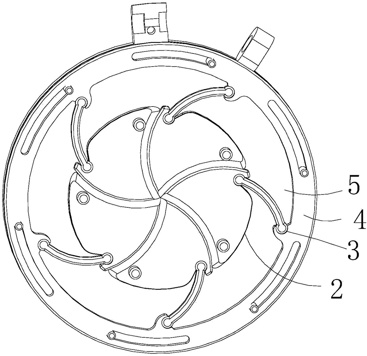
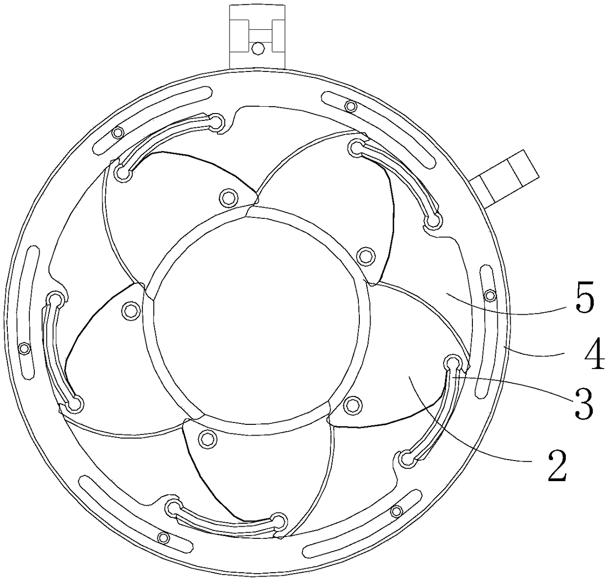
[0039] This embodiment relates to a circular cutting tool, which mainly includes a base, a rotating mounting part and a blade set. The rotating mounting part is rotatably arranged on the base, and a transparent housing cavity is formed in the middle of the rotating mounting part; the blade set is Housed in the containing cavity, it is composed of a plurality of blades with blades; each blade is distributed in the circumferential direction of the containing cavity, and forms a relative pivot connection with the base, and each blade is hinged on the rotating mounting part through the connecting part; In the middle of the accommodating cavity, the area of ​​the circular cutting space formed by the blades of the blades dynamically changes due to the rotation of the rotary mounting portion relative to the base.

[0040] When removing cables or pipes, the ring cutting tool of this embodiment drives multiple blades into the surface of the cable or pipe through the rotation of the rotary ...

Embodiment 2

[0049] This embodiment relates to a circular cutting tool, such as Figure 9 to Figure 11 As shown, it has substantially the same structure as the ring cutting tool described in the first embodiment, and the main difference lies in the drive connection pair. In this embodiment, the drive connection pair is configured as a gear pair that meshes with the rotating mounting part 4, Specifically, a plurality of gear teeth are formed in the circumferential direction of the rotation mounting portion 4 to cooperate with the driving rod 7 to drive the rotation mounting portion 4 to rotate relative to the base.

[0050] The structure of the driving rod 7 in this embodiment is as Picture 12 As shown, in order to ensure the smooth rotation of the rotating mounting part 4, a driving gear 701, an auxiliary driving gear 702, and a driving gear 701 located between the driving gear 701 and the auxiliary driving gear 702 are arranged at intervals on the central shaft 704 of the driving rod 7. The...


PUM


Abstract

The invention provides a ring cutting tool. The ring cutting tool comprises a base body and a rotary installation portion rotationally arranged on the base body. A through containing cavity is formed in the middle of the rotary installation portion. A blade group is contained in the containing cavity and composed of multiple blades provided with cutting edge portions. All the blades are distributed in the circumferential direction of the containing cavity, and the blades are connected with the base body and can pivot relative to the base body. Each blade is hinged to the rotary installation portion through a connecting portion. The area of a ring cutting space which is defined by the cutting edge portions of all the blades in the middle of the containing cavity is driven to change dynamically because of rotation, relative to the base body, of the rotary installation portion. According to the ring cutting tool, the multiple blades are driven through rotation of the rotary installation portion to penetrate into a surface layer of a cable or pipe, the blades can easily enter the surface layer for cutting, and the cutting and stripping operation can be conducted on the surface layers, of different hardness degrees, of cables and pipes; and besides, the ring cutting space can change dynamically, so that the ring cutting tool is suitable for removing the surface layers of the cables or pipes of different diameters, the frequency of changing tools can be lowered during layer stripping, and the production efficiency is improved.

Description

Technical field [0001] The invention relates to the technical field of cutting tools, in particular to a circular cutting tool. Background technique [0002] When cables or pipes are used, it is usually necessary to remove the circumferential surface of their ends. Existing stripping tools and devices mostly use "V"-shaped knives or arc blades, which can be used to remove cables or The purpose of the pipe surface. The existing stripping tools and devices have the following shortcomings: the type of the V-shaped knife or the arc blade matches the diameter of the cable and pipe, and different types of blades are required to remove the surface layer of the cables and pipes of different diameters, so the blade replacement frequency High, leading to reduced production efficiency; V-knife or arc blades rely on external force to squeeze the outer surface of the cable or pipe to cut into the surface of the cable or pipe. When the surface of the cable or pipe is soft, the extrusion force...

Claims


Application Information

Patent Timeline
Patent Type & Authority Patents(China)
IPC IPC(8): B26D1/28B26D7/26H02G1/12
CPCB26D1/0006B26D1/28B26D7/2614H02G1/1221H02G1/1241
Inventor 常亚江
Owner MIND ELECTRONICS APPLIANCE CO LTD
Why Eureka
Try Eureka