
Data collection system for vacuum low-temperature environment

A data acquisition system, vacuum cryogenic technology, applied to parts of thermometers, thermometers, simulators of space navigation conditions, etc., can solve the problems of large temperature measurement range, failure to meet test requirements, large measurement errors, etc., and achieve high compatibility Effects on Sex and Reliability

Inactive Publication Date: 2017-05-03
BEIJING INST OF SPACECRAFT ENVIRONMENT ENG
View PDF4 Cites 15 Cited by
  • Summary
  • Abstract
  • Description
  • Claims
  • Application Information

AI Technical Summary

Problems solved by technology

The advantages of infrared camera temperature measurement are: the measurement process does not contact the surface to be measured, and does not destroy the temperature field distribution of the surface to be measured; the temperature resolution is high, the temperature measurement range is large, and the temperature field on the surface of the object can be displayed intuitively in different ways; The shortcomings of the camera temperature measurement system are: low accuracy and large measurement error
[0007] With the development of the spacecraft vacuum thermal test, in order to truly simulate the attitude of the spacecraft test piece or flight process, or to measure the thermal deformation, the test piece needs to rotate during the test process. The current thermocouple, platinum resistance, thermal The sensitive resistance temperature measurement system cannot meet the needs of such tests
Although infrared camera temperature measurement can be used to measure the temperature of rotating specimens, its measurement error is large and the accuracy is low, and it cannot meet the test requirements.

Method used


Image

  • Data collection system for vacuum low-temperature environment
  • Data collection system for vacuum low-temperature environment
  • Data collection system for vacuum low-temperature environment

Examples


Embodiment Construction

[0019] The following introduces specific embodiments as the content of the present invention, and the content of the present invention will be further clarified through specific embodiments below. Of course, the description of the following specific embodiments is only to illustrate the content of different aspects of the present invention, and should not be construed as limiting the scope of the present invention.

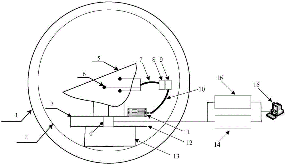
[0020] figure 1 Shown is the principle diagram of the data acquisition system for the vacuum cryogenic environment of the present invention. The data acquisition system includes a data collector 11, an integrated controller 14 and a power controller. The data acquisition system also includes vacuum vessel 1, heat sink 2, turntable 3, conductive slip ring 4, test piece 5, temperature measuring sensor 6, test piece measuring cable 7, test piece electrical connector 8, collector electrical connector 9, Collector measuring cable 10, turntable moving plate 12, turntable ...


PUM


Abstract

The invention discloses a data collection system for a vacuum low-temperature environment. The data collection system comprises a vacuum container, a rotary table, a conductive sliding ring, a test piece, a temperature measurement sensor, a test piece measurement cable, a data collector, a rotary table movable disc, a comprehensive controller and an upper computer. The rotary table and the temperature measurement sensor are located inside the vacuum container, the comprehensive controller and the upper computer are located outside the vacuum container, the test piece is placed on the rotary table movable disc, the temperature measurement sensor adhering to the surface of the test piece is connected to the data collector through the test piece measurement cable, the data collector sends data to the comprehensive controller in an RS485 bus mode through the conductive sliding ring, and the comprehensive controller is in communication with the upper computer in a LAN mode. The data collection system is used for measuring the temperature of a rotary spacecraft test piece, and the gap in measurement for the temperature of a vacuum thermal test rotary test piece of a domestic spacecraft is filled.

Description

Technical field [0001] The invention relates to a ground test field of space environment simulation of a spacecraft, in particular to a data acquisition system used in a vacuum low-temperature environment, in particular to temperature measurement of a spacecraft specimen that needs to be rotated in a vacuum thermal test. Background technique [0002] The vacuum thermal test is one of the large-scale ground tests that must be carried out during the development of the spacecraft. In the vacuum thermal test, data collection, especially temperature data collection. If the temperature data is inaccurate, the conclusions made based on the test data may not be consistent with the actual conditions of the flight, and wrong decisions may be made based on such conclusions, which may eventually cause some components on the spacecraft to be overheated or It is too low to work properly. At present, the temperature measurement of spacecraft in the vacuum thermal test mainly has the following ...

Claims


Application Information

Patent Timeline
IPC IPC(8): B64G7/00G01K1/02G01K1/024
Inventor 朱熙刘波刘畅吴东亮廖韬谢吉慧郄殿福梅志光
Owner BEIJING INST OF SPACECRAFT ENVIRONMENT ENG
Learn More