
Pulp bleaching apparatus with flushing mechanism

A pulp bleaching and pulp technology, which is applied in pulp bleaching, washing/replacement of pulp treatment liquid, etc., can solve the problems of poor pulp quality, reducing bleaching time, and reducing the probability of pulp input pipe clogging, etc.

Inactive Publication Date: 2017-05-03
安徽鑫久亚光电科技有限公司
View PDF4 Cites 4 Cited by
  • Summary
  • Abstract
  • Description
  • Claims
  • Application Information

AI Technical Summary

Problems solved by technology

[0003] In order to make up for the above-mentioned defects of uneven mixing with bleaching solution when the pulp concentration is too high, poor pulp quality due to uneven concentration of pulp and bleaching agent, and low production efficiency due to easy blockage of the outlet of the pulp input pipe, the present invention proposes a washing machine with a flushing mechanism. pulp bleaching plant
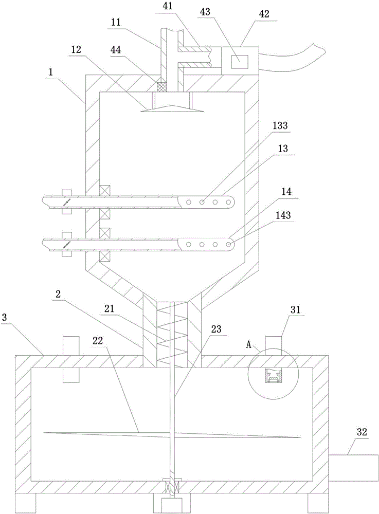
In this technical solution, in order to solve the defect that the pulp concentration is too high and the bleaching solution is not uniformly mixed, and the high-concentration pulp is easy to be blocked, the pulp separating plate is used to replace the nozzle of the original pulp input pipe, so as to reduce the probability of blockage of the pulp input pipe, and at the same time, the pulp entering When the time is evenly distributed by the separating disc, it disperses along the edge of the separating disc and flows into the bleaching chamber, so that the pulp is dispersed and mixed with the bleaching liquid, and the two are mixed more evenly, reducing the bleaching time and increasing the bleaching efficiency.

Method used


Image

  • Pulp bleaching apparatus with flushing mechanism
  • Pulp bleaching apparatus with flushing mechanism
  • Pulp bleaching apparatus with flushing mechanism

Examples


Embodiment approach

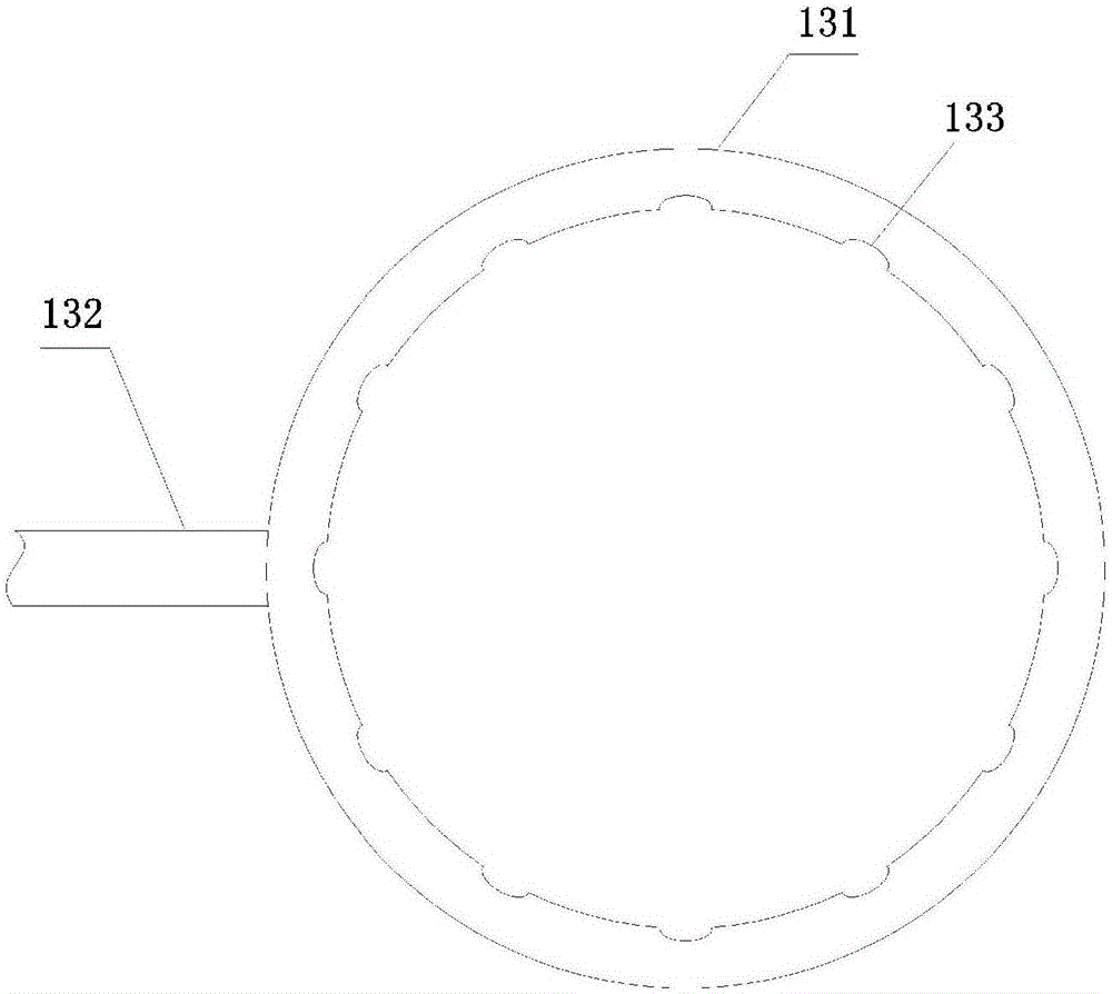
[0018] to combine figure 1 , an embodiment of the present invention. A pulp bleaching device with a flushing mechanism, comprising a bleaching assembly and a flushing assembly, the bleaching assembly includes a bleaching chamber 1, which is connected to a dilution chamber 3 below the bleaching chamber through a delivery pipeline 2, and a pulp is connected to the top of the bleaching chamber Input pipe 11, the bleaching chamber is sequentially provided with a pulp separation plate 12, a bleaching liquid input pipe 13 and a primary dilution liquid input pipe 14 from top to bottom, the pulp separation plate includes a conical top, and the conical top is correspondingly arranged Below the pulp input pipe, the bleaching liquid input pipe includes a liquid injection pipe 131 and an infusion pipe 132 connected with the liquid outlet pipe. A plurality of liquid injection ports 133 are opened on the liquid injection pipe, and the primary The bleaching liquid input pipe includes a liqu...


PUM


Abstract

The invention especially relates to a pulp bleaching apparatus with a flushing mechanism, belonging to the field of pulp bleaching equipment. The pulp bleaching apparatus with the flushing mechanism comprises a bleaching assembly and a flushing assembly, wherein the bleaching assembly comprises a bleaching chamber and a dilution chamber arranged below and connected with the bleaching chamber via a conveying pipeline; the top of the bleaching chamber is connected with a pulp inlet pipe; the interior of the bleaching chamber is provided with a pulp distributing disc, a bleaching solution inlet pipe and a primary dilution solution inlet pipe from top to bottom; the pulp distributing disc comprises a taper top which is correspondingly arranged below the pulp inlet pipe; the bleaching solution inlet pipe comprises a solution spraying pipe and a solution conveying pipe connected with a solution outlet pipe; the solution spraying pipe is provided with a plurality of solution spraying nozzles; the primary dilution solution inlet pipe comprises a solution sprinkling pipe and a solution inlet pipe connected with the solution sprinkling pipe; and the solution sprinkling pipe is provided with a plurality of solution sprinkling nozzles.

Description

technical field [0001] The invention belongs to the technical equipment field of pulp bleaching for papermaking, in particular to a pulp bleaching device with a flushing mechanism. Background technique [0002] At present, the pulping stage in the bleaching process for softwood pulp and hardwood pulp generally includes several steps of "raw material selection→cooking and separating fibers→washing→bleaching→washing and screening→concentrating or copying into pulp sheets→storage for future use", among which In the bleaching step, the uncolored pulp is treated with a bleaching agent to remove the colored substances in the pulp to improve the brightness. This process usually requires the use of special bleaching equipment for pulp bleaching. The traditional pulp bleaching tower directly uses a pulp input port and Bleaching agent inlet, the two pipes are mixed with each other to get bleached pulp. In this process, high pulp concentration helps to reduce the use of bleaching solu...

Claims


Application Information

Patent Timeline
IPC IPC(8): D21C9/02D21C9/10
CPCD21C9/02D21C9/10
Inventor 何家寨
Owner 安徽鑫久亚光电科技有限公司
Learn More