Differential pressure balance valve

A balancing valve and differential pressure technology, which is applied in the field of differential pressure balancing valves, can solve the problems of not being resistant to high temperature, easy to wear, and short life of the diaphragm differential pressure balancing valve.

Active Publication Date: 2017-05-03
常州汉腾自动化设备有限公司
View PDF6 Cites 1 Cited by
  • Summary
  • Abstract
  • Description
  • Claims
  • Application Information

AI Technical Summary

Problems solved by technology

However, the diaphragm is made of rubber, which is not resistant to high temperature and easy to wear, which makes the service life shorter
[0003] To sum up, how to solve the

Method used


Image

  • Differential pressure balance valve
  • Differential pressure balance valve

Examples


Embodiment Construction

[0027] In order to enable those skilled in the art to better understand the technical solutions of the present invention, the present invention will be further described in detail below in conjunction with the accompanying drawings.

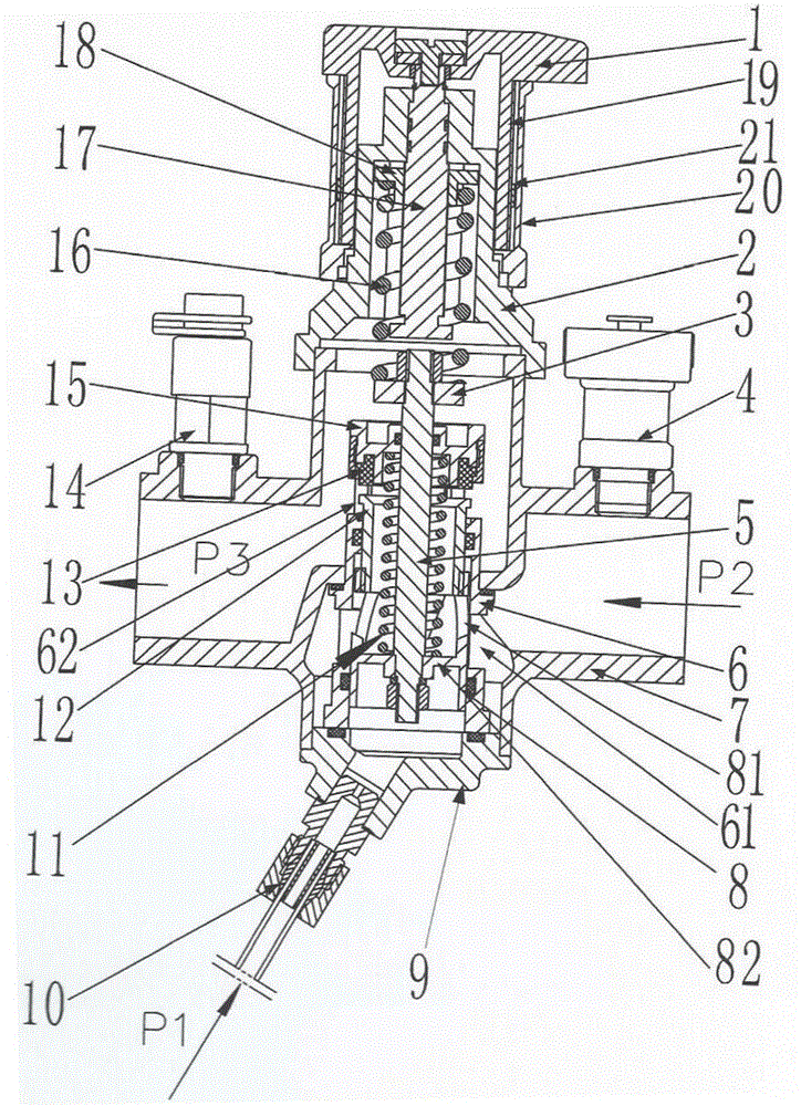
[0028] Please refer to figure 1 , this embodiment provides a differential pressure balance valve, which is used to ensure that the differential pressure between the water inlet chamber and the water supply pipeline is maintained at a preset value. The differential pressure balancing valve includes a valve body 7, a valve core and an operating part.

[0029] Wherein, the valve body 7 usually has a valve body top cover 2 and a valve body bottom cover 9, and the valve body top cover 2 and the valve body bottom cover 9 are detachably fixed to facilitate the installation of the valve core. Of course, both the valve body top cover 2 and the valve body bottom cover 9 are hermetically installed.

[0030] The valve core is arranged in the valve chamber ...


PUM


Abstract

The invention discloses a differential pressure balance valve. The differential pressure balance valve comprises a valve body, a valve element installed in a valve cavity of the valve body and an operating part; the valve cavity comprise a water inflow cavity and a water outflow cavity which are separated in a sealed manner; the valve element comprises a valve element outer barrel, a valve element inner barrel and a valve cone; the outer barrel is provided with a water inlet communicated with the water inflow cavity, and a water outlet communicated with the water outflow cavity; an inner cavity of the outer barrel is a water flow passageway communicated with the water inlet and the water outlet; the inner barrel is provided with an avoiding hole communicated with the water inlet; the valve cone can be driven by the inner barrel to move relative to the axial direction of the outer barrel to adjust the opening degree of the water outlet; the inner barrel is provided with a pressure sensing plate; the differential pressure balance valve further comprises a center column fixed to the pressure sensing plate and stretching into the water flow passageway; a valve base is arranged at the top end of the center column; a first elastic part is arranged between the valve base and the pressure sensing plate in a clamped manner; the pressure sensing plate, the outer barrel and a valve body bottom cover of the valve body form a pressure sensing cavity; and the pressure sensing cavity is communicated with a water supply pipeline. The operating part is used for determining an upper stop point and a lower stop point when the center column moves along with the inner barrel. The above scheme can solve the problem that a current diaphragm differential pressure balance valve is short in service life.

Description

technical field [0001] The invention relates to the technical field of valve design, in particular to a differential pressure balancing valve. Background technique [0002] The application of diaphragm pressure balance valve in heating and air conditioning systems can absorb the external disturbance of the system network and weaken the internal disturbance of the controlled part, so that the system pressure difference (referring to the water flow pressure of the water supply pipeline and the water inlet pipeline) Poor) to maintain the set value, so as to ensure the hydraulic balance of the system. Since the diaphragm pressure balance valve has the function of automatically constant the pressure difference of the controlled loop, no matter how the system pressure changes, and no matter how the branches other than the controlled loop are adjusted, the diaphragm pressure balance valve can maintain the controlled pressure. The differential pressure in the control loop is consta...

Claims


Application Information

Patent Timeline
IPC IPC(8): F16K17/30F16K37/00F16K31/60
CPCF16K17/30F16K31/60F16K37/0016
Inventor 徐国丽郭健翔李海清高国友
Owner 常州汉腾自动化设备有限公司
Why Eureka
Try Eureka