Air source heat pump heating system and control method thereof

An air source heat pump and heating system technology, applied in superheaters, refrigerators, refrigeration components, etc., can solve the problems of compressor suction temperature too high, unable to work normally, and unable to guarantee compressor suction temperature refrigerant temperature, etc. Achieve the effect of increasing the evaporation temperature and heat absorption, reducing the risk of liquid hammer, and improving the heating capacity

Inactive Publication Date: 2017-05-03
QINGDAO HAIER NEW ENERGY ELECTRIC APPLIANCE
View PDF6 Cites 5 Cited by
  • Summary
  • Abstract
  • Description
  • Claims
  • Application Information

AI Technical Summary

Problems solved by technology

[0004] Both of the above two systems have certain disadvantages. When the heating return water temperature of the carbon dioxide heat pump system is too high, the temperature of the refrigerant flowing out of the condenser is relatively high. When the temperature is only cooled by the regenerator, the compressor suction temperature will still be too high and cannot work normally. work; the heating and air conditioning system cannot guarantee the proper compressor suction temperature and refrigerant temperature before throttling only by the dual-flow evaporator

Method used


Image

  • Air source heat pump heating system and control method thereof
  • Air source heat pump heating system and control method thereof
  • Air source heat pump heating system and control method thereof

Examples


Embodiment 1

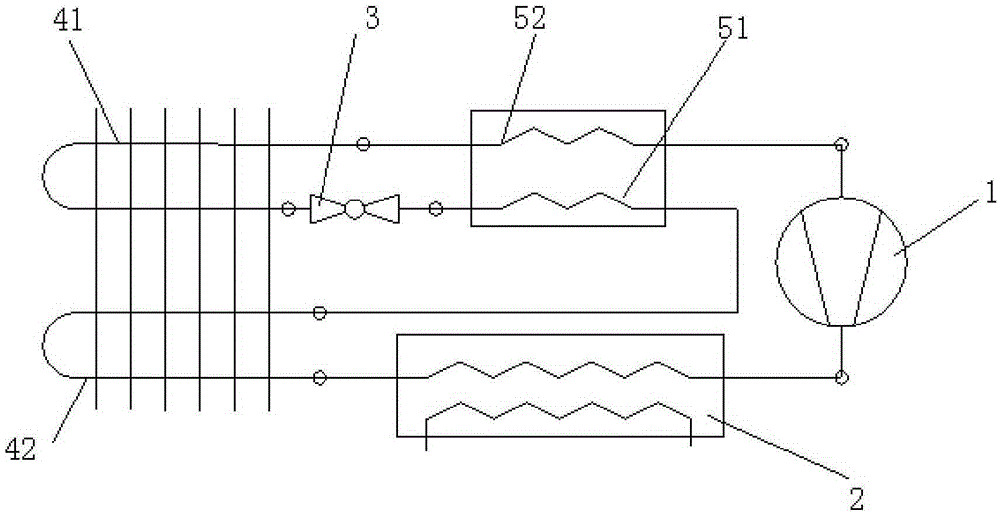
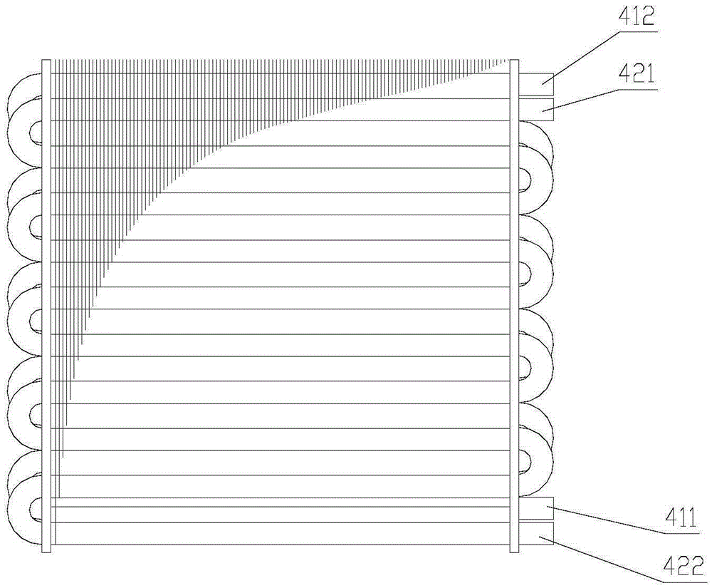
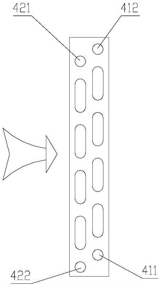
[0029] The preferred embodiment discloses an air source heat pump heating system. Such as figure 1 As shown, the air source heat pump heating system includes a compressor 1, a condenser 2, a throttling element 3 and a first evaporator 41 which are sequentially connected in series to form a circulation loop, wherein the throttling element 3 is preferably an expansion valve.

[0030] Between the refrigerant outlet of the condenser 2 and the refrigerant inlet of the throttling element 3 is communicated with the first branch of the regenerator 51; between the inlet of the compressor 1 and the refrigerant outlet of the first evaporator 41 is communicated with a regenerator The second branch 52; the second evaporator 42 is communicated between the refrigerant outlet of the condenser 2 and the refrigerant inlet of the first branch 51 of the regenerator, and the second evaporator 42 is used for the refrigerant flowing out of the condenser 2 heat exchange.

[0031] The specific conne...

Embodiment 2

[0041]This preferred embodiment discloses an air source heat pump heating system. In the air source heat pump heating system, the refrigerant can be but not limited to CO 2 , its structure is basically the same as that of the preferred embodiment 1. The air source heat pump heating system includes a compressor, a condenser, a throttling element, and a first evaporator connected in series to form a circulation loop, and a regenerator is connected between the refrigerant outlet of the condenser and the refrigerant inlet of the throttling element. A branch; between the inlet of the compressor and the refrigerant outlet of the first evaporator, there is a second branch of the regenerator; between the refrigerant outlet of the condenser and the refrigerant inlet of the first branch of the regenerator, there is a The second evaporator is used for exchanging heat for the refrigerant flowing out of the condenser.

[0042] The difference is that the first evaporator and the second eva...


PUM


Abstract

The invention discloses an air source heat pump heating system and a control method thereof, and belongs to the technical field of heat pumps. The air source heat pump heating system is designed to solve the problems that an existing air source heat pump heating system is too high in condenser outlet refrigerant equipment and too low in evaporation temperature. According to the air source heat pump heating system, a heat regenerator first branch communicates between a refrigerant outlet of a condenser and a refrigerant inlet of a throttle element; a heat regenerator second branch communicates between an inlet of a compressor and a refrigerant outlet of a first evaporator; and a second evaporator communicates between the refrigerant outlet of the condenser and a refrigerant inlet of the heat regenerator first branch and is used for carrying out heat exchange on refrigerant flowing out of the condenser. According to the control method of the air source heat pump heating system, the refrigerant flowing out of the condenser sequentially flows through the second evaporator and the heat regenerator first branch and then flows into the throttle element. The air source heat pump heating system can guarantee the proper refrigerant temperature generated before throttling and improve the evaporator heating capacity.

Description

technical field [0001] The invention relates to the field of heat pumps, in particular to an air source heat pump heating system and a control method based on the air source heat pump heating system. Background technique [0002] In recent years, heat pump technology has attracted much attention as a new energy technology, and its application fields are also very wide. The air source heat pump heating system mainly includes a compressor, a condenser, a throttling element and an evaporator. [0003] There is an existing carbon dioxide heat pump system, which includes a regenerator in addition to a compressor, a condenser, a throttling element and an evaporator, and controls the temperature of the refrigerant entering the throttling element and the suction temperature of the compressor through the regenerator; There is a heating and air-conditioning system, which is equipped with a dual-flow evaporator, that is, the bottom part of the evaporator is connected to the outlet of ...

Claims


Application Information

Patent Timeline
Patent Type & Authority Applications(China)
IPC IPC(8): F25B13/00F25B40/06F25B9/00
CPCF25B13/00F25B9/008F25B40/06F25B2313/021
Inventor 杨磊王建良白龙亮陈康
Owner QINGDAO HAIER NEW ENERGY ELECTRIC APPLIANCE
Why Eureka
Try Eureka