Driving structure of electric lifting table

A driving structure and a technology for lifting tables, which are applied to tables, service tables, and tables with variable table heights, etc., can solve problems such as poor synchronization, high production costs, and motor heat damage, so as to help balance output and improve market competition. The effect of low power and production cost

Pending Publication Date: 2017-05-10
黄顺贤
View PDF0 Cites 3 Cited by
  • Summary
  • Abstract
  • Description
  • Claims
  • Application Information

AI Technical Summary

Problems solved by technology

But it has the following problems: 1. The conveyor belt is a vulnerable part and has poor synchronization
2. The motor power is required to be large,

Method used


Image

  • Driving structure of electric lifting table
  • Driving structure of electric lifting table
  • Driving structure of electric lifting table

Examples


Embodiment Construction

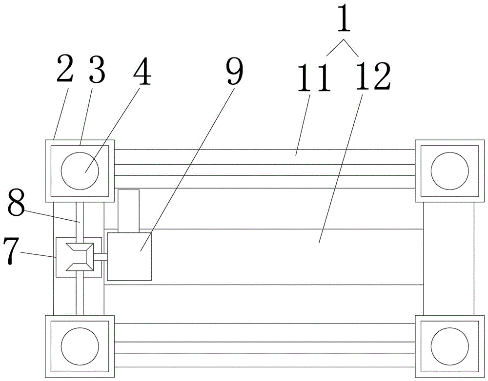
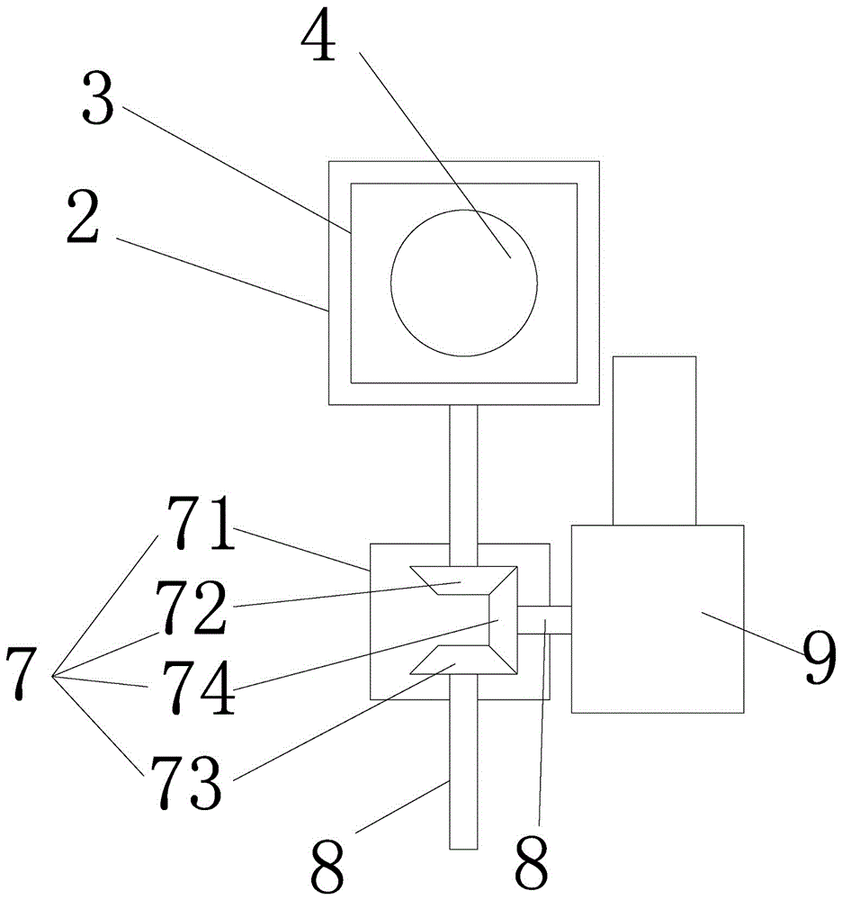
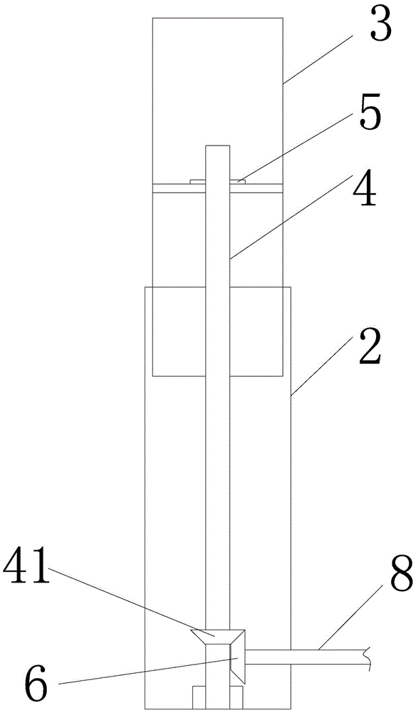
[0013] The present invention will be specifically and further described below in conjunction with the accompanying drawings. An electric lift table drive structure, characterized in that it includes a main bracket 1 and fixed legs 2 arranged at its four corners, the fixed legs 2 are provided with a lifting leg 3, and the fixed leg 2 is provided with a lifting screw 4 and a The nut 5 in the lifting leg 3 is screwed; the driven bevel gear 41 is installed on the lifting screw 4 to mesh with the driving bevel gear 6 in the fixed leg 2, and the main bracket 1 is provided with a gearbox 7. Transmission rods 8 extending from both sides of the gearbox are connected to the active bevel gears 6 in the left and right fixed legs, and the gearbox 7 is connected to the drive motor 9 through the transmission rods 8 .

[0014] The gearbox 7 is arranged at the midpoint of the left and right fixed legs 1, and the gearbox 7 is fixed on the main bracket 1.

[0015] Described gearbox 7 comprises ...


PUM


Abstract

The invention provides a driving structure of an electric lifting table. The driving structure includes a main support 1 and fixing legs arranged at the four corners of the main support, lifting legs are arranged in the fixing legs in a sleeving mode, and the fixing legs are internally provided with lifting screw rods which are in threaded connection with nuts arranged in the lifting legs; the lifting screw rods are provided with conical driven gears which are meshed with conical driving gears arranged in the fixing legs; a transmission gearbox is arranged on the main support, the two sides of the transmission gearbox extend out of transmission rods to be connected with the conical driving gears in the left fixing leg and the right fixing leg, and the transmission gearbox is connected with a driving motor through the transmission rods. The driving structure of the electric lifting table has the advantages that a reducer is arranged between the motor and driving screw rods and can effectively reduce the operation resistance of the motor and make a lifting device run smoothly and quietly; the reducer is arranged between the left fixing leg and the right fixing leg and located in the main support, and accordingly installation with a housing is convenient to achieve, and balanced output of power is easily achieved.

Description

technical field [0001] The invention relates to an electric heating table accessory, in particular to an electric lifting table driving structure. Background technique [0002] In the current prior art, a lifting type electric heating table includes a panel, a base, a lifting nut, a lifting screw, a driving mechanism, an inner support sleeve, an outer support sleeve and a heating device arranged on the outer support sleeve; the inner support sleeve is fixedly connected to the panel , the outer support sleeve is fixedly connected with the base, the lifting nut is arranged in the inner support sleeve, the lifting screw rod cooperates with the lifting screw, and the driving mechanism includes a motor, a driving wheel, several transmission wheels and a conveyor belt. But it has the following problems: 1. The conveyor belt is a vulnerable part and has poor synchronization. 2. The motor power is required to be large, and the motor is prone to heat damage and other disadvantages d...

Claims


Application Information

Patent Timeline
IPC IPC(8): A47B9/04A47B31/02
CPCA47B9/04A47B31/02A47B2009/043A47B2009/046
Inventor 黄顺贤
Owner 黄顺贤
Why Eureka
Try Eureka