Novel telescopic pipeline cleaning robot

A technology of telescopic pipes and robots, which is applied in the field of machinery, can solve problems such as high labor intensity, paralyzed traffic, and complicated operations, and achieve the effects of reducing labor intensity, improving the working environment, and improving cleaning efficiency

Active Publication Date: 2017-05-10
SHANDONG UNIV OF SCI & TECH
View PDF11 Cites 60 Cited by
  • Summary
  • Abstract
  • Description
  • Claims
  • Application Information

AI Technical Summary

Problems solved by technology

Due to the long-term discharge of domestic and industrial waste and the accumulation of sewage, a lot of garbage and silt accumulate in the drainage pipes, which block the pipes and affect the normal use of the drainage system. Especially in the rainy season, it is more likely to cause waterlogging in the city and paralyze the traffic. Regular drainage is required pipes to clean
Common urban drainage pipe cleaning methods mainly include hydraulic dredging, manual shovel digging, push rod dredging, etc., but these traditional methods consume a lot of manpower and financial resources, low cleaning efficiency, high manual labor intensity, and great safety hazards in the pipeline.
At present, there are some devices on the market for cleaning the inside of the pipeline. The existing pipeline machines have only one degree of freedom due to the mechanical actuator. When cleaning the pipeline wall, it is necessary to continuously adjust the position of the machine, which makes the operation complicated. Cleaning efficiency is low
For long-length pipes, pipes with large curvature, pipes with multiple branches and pipes with variable diameters, it is difficult for existing cleaning equipment to clean the inner wall of the above-mentioned pipes.

Method used


Image

  • Novel telescopic pipeline cleaning robot
  • Novel telescopic pipeline cleaning robot

Examples


Embodiment Construction

[0017] The present invention is described in detail below in conjunction with accompanying drawing:

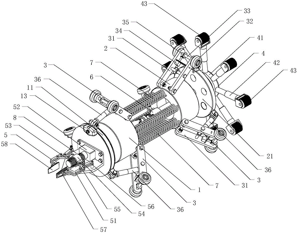
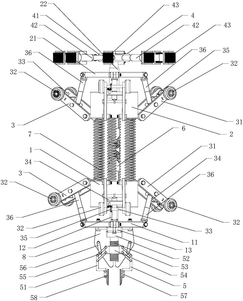
[0018] combine figure 1 and figure 2 , a new type of telescopic pipe cleaning robot, including a first body 1, a second body 2, a traveling mechanism 3, a cleaning device 4 and a manipulator 5, the first body 1 and the second body 2 are cylindrical structures, and The two are arranged in a front-to-back and positively opposite manner. The first body 1 and the second body 2 are connected together by a double-joint universal joint 6 , and the double-joint universal joint 6 The front end is fixedly connected with the rear part of the first body 1, and its rear end is fixedly connected with the front part of the second body 2. The double-joint universal joint 6 can make the first body 1 and the second body 2 realize larger Angular range of steering. Six springs 7 are arranged between the first body 1 and the second body 2. In the state of natural elongation, all the springs 7 ...


PUM


Abstract

The invention discloses a novel telescopic pipeline cleaning robot which comprises a first body, a second body, two traveling mechanisms, a cleaning device and a mechanical arm. The first body and the second body are arranged in the front-back direction and connected through a double-joint universal coupler. The traveling mechanisms are arranged on the outer side of the first body and the outer side of the second body correspondingly. The cleaning device is arranged on the rear side of the second body and comprises a cleaning disc and a plurality of telescopic rods. The cleaning disc is connected with a first motor arranged inside the second body. The multiple telescopic rods are evenly arranged on the edge of the cleaning disc in an annular mode. One end of each telescopic rod is fixedly connected with the cleaning disc, and a cleaning wheel is arranged at the other end of each telescopic rod. A bracket is arranged on the front side of the first body, and the mechanical arm is installed on the bracket. When the novel telescopic pipeline cleaning robot is used for cleaning different pipelines, the inner walls of the pipelines with different diameters and curvature degrees can be cleaned by adjusting the lengths of the telescopic rods, the novel telescopic pipeline cleaning robot is suitable for variable-diameter pipelines of complex structures, the adaptability is high, and the cleaning efficiency is high.

Description

technical field [0001] The invention relates to the technical field of machinery, in particular to a novel scalable pipeline cleaning robot. Background technique [0002] With the rapid development of economy and society, urban drainage pipes, as an important part of urban infrastructure, play an irreplaceable role in municipal engineering construction. Due to the long-term discharge of domestic and industrial waste and the accumulation of sewage, a lot of garbage and silt accumulate in the drainage pipes, which block the pipes and affect the normal use of the drainage system. Especially in the rainy season, it is more likely to cause waterlogging in the city and paralyze the traffic. Regular drainage is required The pipes are cleaned. Common urban drainage pipeline cleaning methods mainly include hydraulic dredging, manual shovel digging, and push rod dredging. However, these traditional methods consume a lot of manpower and financial resources, have low cleaning efficienc...

Claims


Application Information

Patent Timeline
Patent Type & Authority Applications(China)
IPC IPC(8): B08B9/051B08B9/04
CPCB08B9/04B08B9/051
Inventor 姜帅陈修龙高文花宋浩贾永皓高昊陈天祥李跃文蔡京成邹佳昆
Owner SHANDONG UNIV OF SCI & TECH
Why Eureka
Try Eureka