
Improved die with automatic stripping function

An improved and automatic technology, applied in forming tools, manufacturing tools, presses, etc., can solve the problems of low part processing efficiency, high operation risk, high maintenance cost, etc., and achieve low manufacturing cost, high precision and simple structure Effect

Active Publication Date: 2017-05-10
顺庭模具科技南通有限公司
View PDF7 Cites 2 Cited by
  • Summary
  • Abstract
  • Description
  • Claims
  • Application Information

AI Technical Summary

Problems solved by technology

When the contact area between the upper and lower dies and the parts of the existing stamping die is relatively large, it is easy for the parts to stick to the die and not easy to fall off. Manual detachment is required, the operation is dangerous and the processing efficiency of the parts is low. In addition, the existing The automatic stripping mold needs to use a separate stripping mechanism for stripping work, which has problems such as low work efficiency, high manufacturing cost, and high maintenance cost.

Method used


Image

  • Improved die with automatic stripping function
  • Improved die with automatic stripping function
  • Improved die with automatic stripping function

Examples


Embodiment Construction

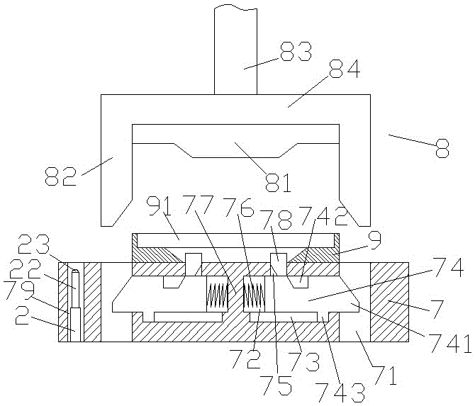
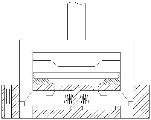
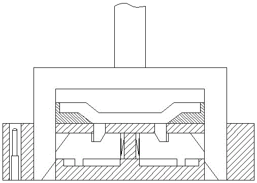
[0019] Such as Figure 1-Figure 4 As shown, an improved automatic stripping mold of the present invention includes an upper frame body 8 and a lower frame body 7 arranged below the upper frame body 8. The upper frame body 8 includes a pressing plate 84, an upper mold body 81 And lifting push rod 83, described pressing plate 84 both sides are all fixedly provided with the inclined-plane pushing column 82 that extends downwards, and described lower frame body 7 top is provided with the lower mold body 9 that is oppositely arranged with described upper mold body 81 The lower frame body 7 opposite to the inclined-plane pushing column 82 is provided with a through hole 71 for matching connection with the inclined-plane pushing column 82, and the lower frame body 7 between the through-holes 71 Sliding grooves 72 arranged symmetrically on the left and right are arranged inside, and partitions 77 fixedly connected with the lower frame body 7 are arranged between the sliding grooves 72...


PUM


Abstract

The invention discloses an improved die with an automatic stripping function. The improved die with the automatic stripping function comprises an upper frame body and a lower frame body arranged below the upper frame body. A pressing plate, an upper die body and a lifting push rod are arranged in the upper frame body. Oblique-surface pushing and pressing columns which extend downwards are fixedly arranged on the two sides of the pressing plate correspondingly. A lower die body which is opposite to the upper die body is arranged at the top of the lower frame body. Through holes are formed in the positions, opposite to the lower portions of the oblique-surface pushing and pressing columns, in the lower frame body. Sliding grooves are formed in the portion, between the through holes, in the lower frame body in a bilaterally symmetrical mode. A partition plate which is fixedly connected with the lower frame body is arranged between the sliding grooves. A through hole which penetrates through the wall of the lower frame body and communicates with the bottom of the interior of the lower die body is formed in the top of each sliding groove, and an oblique-surface stripping block is arranged in the through hole. A sliding guide groove is formed in the bottom of each sliding groove, a sliding block is slidably arranged in each sliding groove, an ejection spring is arranged between each sliding block and the partition plate, and an oblique-surface sliding groove is formed in the top of each sliding block. The improved die with the automatic stripping function is simple in structure, and automatic stripping can be achieved after punching is completed; and the manufacturing cost is low, and maintenance is convenient.

Description

technical field [0001] The invention relates to the technical field of molds, in particular to an improved automatic stripping mold. Background technique [0002] Stamping processing in mechanical processing occupies an important position in the processing industry of the national economy. The stamping process is adopted, which has the advantages of high precision, high efficiency, good quality, material saving and low cost. Stamping die is an indispensable process equipment for stamping production, and it is a technology-intensive product. The quality, production efficiency and production cost of stamping parts are directly related to the design and manufacture of molds. When the contact area between the upper and lower dies and the parts of the existing stamping die is relatively large, it is easy for the parts to stick to the die and not easy to fall off. Manual detachment is required, the operation is dangerous and the processing efficiency of the parts is low. In addi...

Claims


Application Information

Patent Timeline
IPC IPC(8): B21D45/04B21D37/12
CPCB30B15/32B21D45/04B21D45/06B21D37/12
Inventor 俞海东
Owner 顺庭模具科技南通有限公司
Learn More