
Micro-wire electrode processing device

A processing device and micro-wire electrode technology, which is applied in the direction of manufacturing tools and other manufacturing equipment/tools, etc., can solve the problems of burning electrode wire, uncontrollable current size, and peeling of insulating layer, etc., and achieve the effect of preventing burning

Inactive Publication Date: 2017-05-10
科斗(苏州)脑机科技有限公司
View PDF7 Cites 0 Cited by
  • Summary
  • Abstract
  • Description
  • Claims
  • Application Information

AI Technical Summary

Problems solved by technology

[0002] With the continuous development of science and technology and the deepening of neuroscience research, the preparation technology of microwire electrodes is also continuously improving. Microwire electrodes are one of the indispensable tools for neuroscience research. It has small size, light weight, The electrode wire is soft and so on. The preparation includes many processes. Among them, the cutting process is one of the important processes. Since the electrode wire array of the micro-wire electrode cannot be bent, the ordinary cutting process cannot meet the requirements. Generally, the wire cutting method is used. However, the ordinary wire cutting technology cannot control the length of the microwire electrode wire, and the current size cannot be controlled during wire cutting, resulting in an uncontrollable temperature during cutting. During cutting, heat accumulation will burn the electrode wire. After cutting, the insulation cannot be Layer peeling, making it difficult to carry out the subsequent sharpening process

Method used


Image

  • Micro-wire electrode processing device
  • Micro-wire electrode processing device

Examples


Embodiment Construction

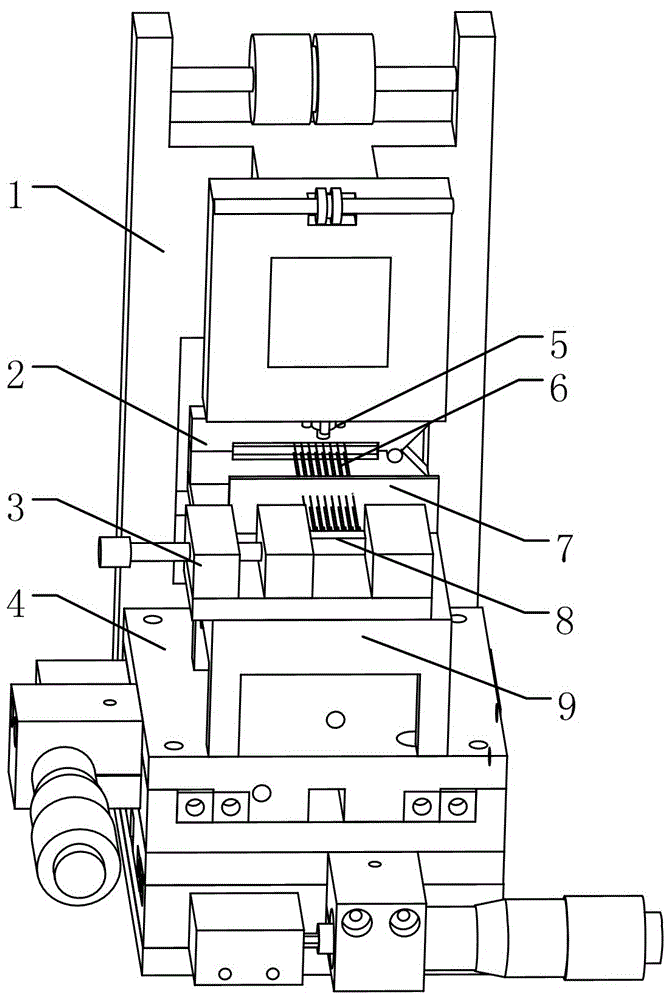
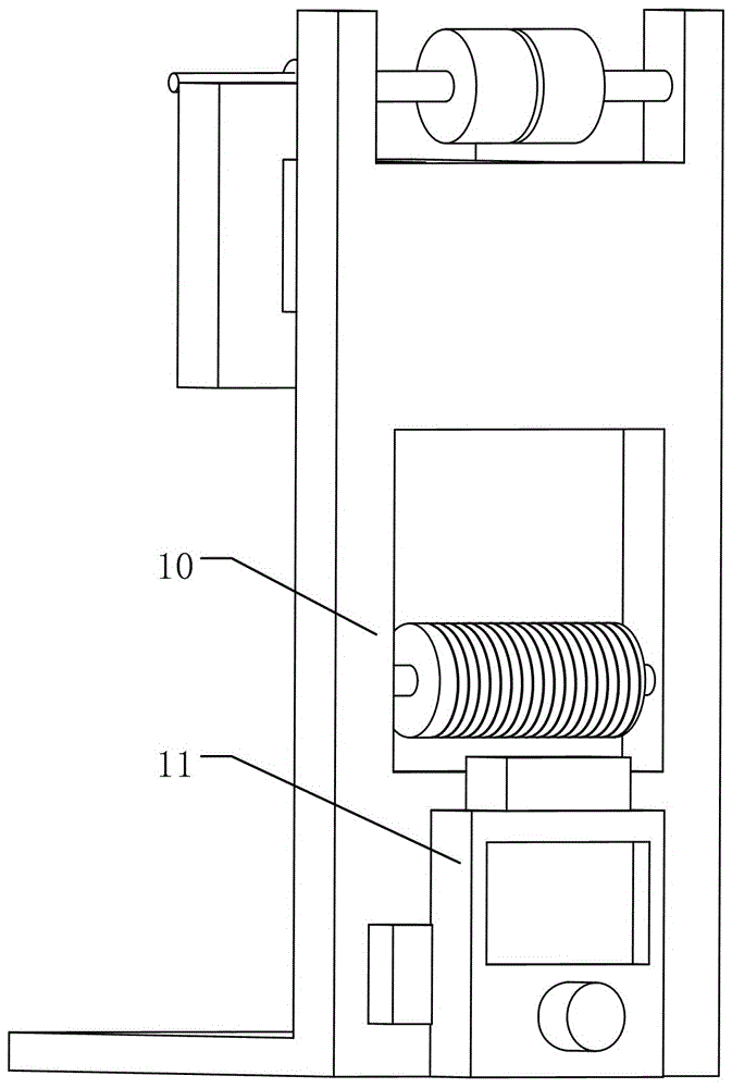
[0014] Such as figure 1 , 2 As shown, a microwire electrode processing device can be used to weld the electrode wire 6 to the electrode pin header 8, including: a working platform 4; an electrode clamp 3, which is installed on the working platform 4 and configured as the electrode clamp 3. The electrode pin row 8 can be fixed; the array hole plate 7 is installed on the workbench 9, and each electrode wire 6 passes through the corresponding hole of the array hole plate 7 in sequence, so that a plurality of the electrode wires 6 The electrode wires 6 form an electrode wire array; moreover, each of the electrode wires 6 passes through corresponding holes in the array hole plate 7 in turn and is welded to the electrode pin header 8 . An electrode wire clamp 2, installed on the working platform 9, configured such that the electrode wire clamp 2 can clamp the electrode wire 6; a wire cutting device 1, the wire cutting device 1 includes a controller 10 and a wire cutting machine 11...


PUM


Abstract

The invention relates to a micro-wire electrode processing device which can be used for welding electrode wires to electrode pins. The micro-wire electrode processing device includes: a work platform; an electrode clamp which is arranged on the work platform and is configured to fix the electrode pins; an array hole plate which is arranged on a workbench, each electrode wire can successively pass through corresponding hole of the array hole plate so as to allow a plurality of electrode wires to form an electrode wire array; an electrode wire clamp which is arranged on the work platform, and is configured to clamp the electrode wires; and a wire cutting device which includes a controller and a wire cutting machine, and is configured to allow the controller to control the current of the wire cutting machine, wherein the wire cutting machine can cut off the electrode wires under the control of the controller. The work platform is fixed on an upper surface of a two-dimensional movement module, and the two-dimensional movement module is configured to adjust the position of the work platform. The beneficial effects of the invention are that the controller can control the current during cutting so as to prevent the electrode wire from being burned; and a laser device can remove surface insulation layer of the electrode wires.

Description

technical field [0001] The invention relates to a microwire electrode processing device. Background technique [0002] With the continuous development of science and technology and the deepening of neuroscience research, the preparation technology of microwire electrodes is also continuously improving. Microwire electrodes are one of the indispensable tools for neuroscience research. It has small size, light weight, The electrode wire is soft and so on. The preparation includes many processes. Among them, the cutting process is one of the important processes. Since the electrode wire array of the micro-wire electrode cannot be bent, the ordinary cutting process cannot meet the requirements. Generally, the wire cutting method is used. However, the ordinary wire cutting technology cannot control the length of the microwire electrode wire, and the current size cannot be controlled during wire cutting, resulting in an uncontrollable temperature during cutting. During cutting, he...

Claims


Application Information

Patent Timeline
Patent Type & Authority Applications(China)
IPC IPC(8): B21F15/08B23P23/00
CPCB21F15/08B23P23/00
Inventor 冀亮亮徐科飞周莉裴东杰
Owner 科斗(苏州)脑机科技有限公司
Learn More