
Gantry type double-head computer numerical control (CNC) milling machine for hub machining

A CNC milling machine and gantry technology, applied in milling machines, milling machine equipment, metal processing and other directions, can solve the problems of increased tool holder weight, low production efficiency, and inability to adapt to mass production of forged wheels.

Active Publication Date: 2017-05-10
NINGBO DEMA INTELLIGENT MACHINERY CO LTD
View PDF6 Cites 9 Cited by
  • Summary
  • Abstract
  • Description
  • Claims
  • Application Information

AI Technical Summary

Problems solved by technology

[0002] The milling of the forged wheel hub requires two processes of rough machining and finishing. Since the replacement of the end milling head of the milling machine is very troublesome, these two processes are basically processed separately on two milling machines at present. The clamping of the workpiece Completed manually, the workpiece after rough machining on one milling machine needs to be manually transferred to another milling machine for finishing, and the workpiece needs to be re-clamped
Such disadvantages are 1. low production efficiency, 2. high labor intensity of workers, 3. large errors in workpiece clamping, 4. two milling machines plus the position of the wheel hub, occupying a large area, so it cannot adapt to the large forging wheel hub mass production needs
This device fixes multiple milling cutters on the tool holder of a milling machine, which greatly increases the weight of the tool holder, which is easy to shake during milling and cannot control the accuracy of the product.

Method used


Image

  • Gantry type double-head computer numerical control (CNC) milling machine for hub machining
  • Gantry type double-head computer numerical control (CNC) milling machine for hub machining
  • Gantry type double-head computer numerical control (CNC) milling machine for hub machining

Examples


Embodiment Construction

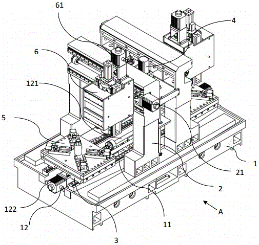
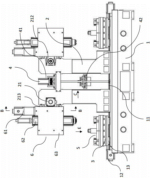
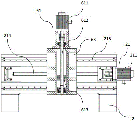
[0024] like figure 1 , figure 2 As shown, the gantry-type double-head CNC milling machine for wheel hub processing includes a base 1, and the base 1 is provided with two symmetrical gantry frames 2, and at the opposite positions of the two gantry frames 2 Both end milling head devices 6 are installed, and an end milling head 62 is installed in the end milling head device 6 . The end milling head 62 on the left side is used for roughing, and the end milling head 62 on the right side is used for finishing, so this device can carry out roughing and finishing operation to workpiece.

[0025] The machine base 1 is provided with a longitudinal guide rail 11, and the longitudinal guide rail 11 runs through two gantry frames 2. Two workbenches 3 are movably installed on the longitudinal guide rail 11, and the workbench 3 on the left side is located on the left side. Below the end milling head 62 , the workbench 3 on the right is located below the end milling head 62 on the right si...


PUM


Abstract

The invention provides a gantry type double-head computer numerical control (CNC) milling machine for hub machining, comprising a bedplate and characterized in that two symmetrical gantry racks are arranged on the bedplate; vertical milling head devices are installed at the reverse positions of the two gantry racks, and longitudinal guide rails are arranged on the bedplate, and run through the two gantry racks; two workbenches are installed on the longitudinal guide rails movably, and fixtures able to clamp workpiece are arranged on the workbenches; a workpiece delivery device is arranged between the two gantry racks, and comprises a clamping device and a lifting device able to drive the clamping device to move upward or downward; the workpiece on the left workbench can be delivered to the right workbench through transition of the workpiece delivery device. The CNC milling machine provided by the invention is mainly used for the hub machining, and the workpiece can be clamped automatically by the fixtures. The workpiece roughly machined is delivered to the right workbench through the workpiece delivery device for fine machining. The CNC milling machine provided by the invention has the advantages of high level of automation and small occupied area.

Description

technical field [0001] The invention relates to a numerical control milling machine for milling workpieces, which is a gantry type numerical control milling machine used for wheel hub processing. Background technique [0002] The milling of the forged wheel hub requires two processes of rough machining and finishing. Since the replacement of the end milling head of the milling machine is very troublesome, these two processes are basically processed separately on two milling machines at present. The clamping of the workpiece It is done manually. After rough machining on one milling machine, the workpiece needs to be manually transferred to another milling machine for finishing, and the workpiece needs to be re-clamped. Such disadvantages are 1. low production efficiency, 2. high labor intensity of workers, 3. large errors in workpiece clamping, 4. two milling machines plus the position of the wheel hub, occupying a large area, so it cannot adapt to the large forging wheel hub...

Claims


Application Information

Patent Timeline
IPC IPC(8): B23C1/08B23Q1/01B23Q1/26B23Q3/06
CPCB23C1/08B23Q1/012B23Q1/017B23Q1/26B23Q3/06B23Q7/04B23Q39/04B23Q39/048
Inventor 董祥义褚国荣
Owner NINGBO DEMA INTELLIGENT MACHINERY CO LTD
Learn More