
Flexible fixture for milling of large complex surface type blade and method of flexible fixture

A flexible fixture and complex curved surface technology, applied in the field of mechanical processing, can solve the problems of large processing deformation, difficult clamping of curved surface parts, and difficulty in guaranteeing the quality of the processed surface, so as to reduce processing deformation, reduce processing deformation, and suppress processing chatter vibration effect

Active Publication Date: 2017-05-10
SHANDONG UNIV
View PDF14 Cites 15 Cited by
  • Summary
  • Abstract
  • Description
  • Claims
  • Application Information

AI Technical Summary

Problems solved by technology

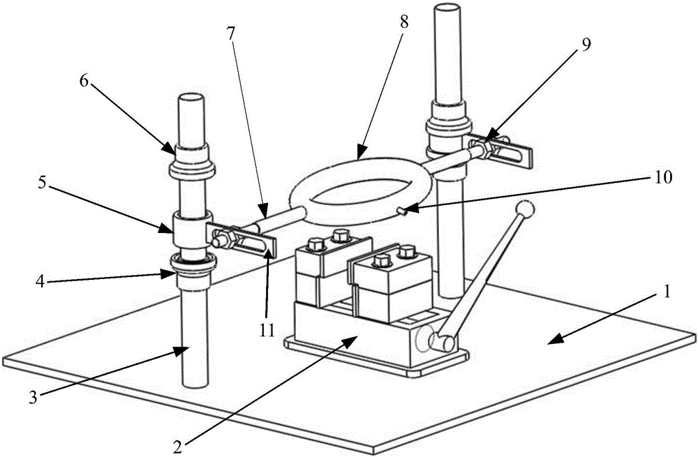
[0011] In order to overcome the deficiencies of the above-mentioned prior art, the present invention provides a flexible fixture for milling blades with large complex curved surfaces. A flexible clamping part is provided to reduce the processing deformation of thin-walled structures such as large blades, and reduce the processing time. chatter, and then solve the problems of large processing deformation and difficult to guarantee the quality of the processed surface caused by weak rigidity in the milling process of large thin-walled blades, as well as the problem of difficult clamping of curved surface parts

Method used


Image

  • Flexible fixture for milling of large complex surface type blade and method of flexible fixture
  • Flexible fixture for milling of large complex surface type blade and method of flexible fixture
  • Flexible fixture for milling of large complex surface type blade and method of flexible fixture

Examples


Embodiment Construction

[0041] It should be pointed out that the following detailed description is exemplary and intended to provide further explanation to the present application. Unless defined otherwise, all technical and scientific terms used herein have the same meaning as commonly understood by one of ordinary skill in the art to which this application belongs.

[0042] It should be noted that the terminology used here is only for describing specific implementations, and is not intended to limit the exemplary implementations according to the present application. As used herein, unless the context clearly dictates otherwise, the singular is intended to include the plural, and it should also be understood that when the terms "comprising" and / or "comprising" are used in this specification, they mean There are features, steps, operations, means, components and / or combinations thereof.

[0043] As introduced in the background technology, there is a problem of processing vibration during the process...


PUM


Abstract

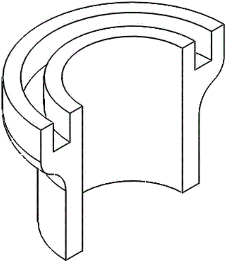
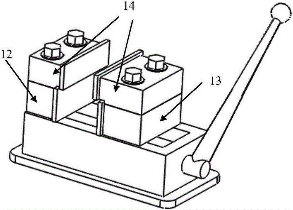
The invention discloses a flexible fixture for milling of a large complex surface type blade and a method of the flexible fixture. The flexible fixture and the method solve the processing vibration problem in a processing procedure of a complex surface thin-walled workpiece, the processing deformation of the thin-walled structure like a large blade can be reduced, and the vibration during processing can be reduced. The flexible fixture is characterized in that the flexible fixture comprises a lower clamping part arranged at a workbench; a flexible clamping part is arranged on the lower clamping part in a matched manner; the two ends of the flexible clamping part are connected with a horizontal movement mechanism; the end part of the horizontal movement mechanism is connected with a vertical movement mechanism; the flexible clamping part comprises an elastic clamping body flexibly bonded with the side wall of the blade; the elastic clamping body flexibly clamps the side wall of the upper part of the blade; the lower clamping part clamps the bottom of the blade; in a processing procedure, the horizontal movement mechanism and the vertical movement mechanism drives the elastic clamping body to adjust a position for clamping the blade, for reserving a to-be-processed area.

Description

technical field [0001] The invention relates to the technical field of mechanical processing, in particular to a flexible fixture and method for milling blades with large complex curved surfaces. Background technique [0002] At present, in the aerospace industry, the cutting task of thin-walled parts is very important, and the variable thickness and thinning processing of thin-walled parts has always been a difficult problem in processing and manufacturing. Thin-walled blades with complex curved surfaces in aerospace structures have large overhangs and poor rigidity, and the main processing method is five-axis milling. The difficult-to-machine structure and complex processing technology make the thin-walled structure prone to deformation, springback and other phenomena during processing. There are problems such as cutting tool and vibration, which lead to deformation of the workpiece and affect the dimensional accuracy of the workpiece, the quality of the cutting surface an...

Claims


Application Information

Patent Timeline
IPC IPC(8): B23Q3/06B23C3/18
CPCB23C3/18B23Q3/063B23Q3/066
Inventor 宋清华高建刘战强万熠史振宇
Owner SHANDONG UNIV
Learn More