Supercharge Your Innovation With Domain-Expert AI Agents!

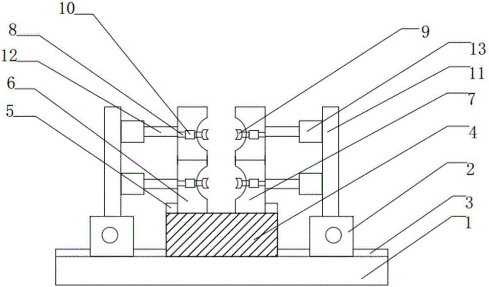
Tube clamping device

A clamping device and pipe technology, applied in the direction of clamping device, positioning device, clamping, etc., can solve the problems that the pipe cannot be well clamped, the manufacturing cost is large, and the application range is small, and the clamping effect is good. Improve work efficiency and high clamping efficiency

Inactive Publication Date: 2017-05-10
天津汇之灵科技有限公司
View PDF0 Cites 18 Cited by
  • Summary
  • Abstract
  • Description
  • Claims
  • Application Information

AI Technical Summary

Problems solved by technology

There are many places to be improved in the traditional clamping device, the operation is relatively cumbersome, the pipes with different diameters cannot be clamped well, the structure is complicated, the manufacturing cost is high, and the application range is small

Method used


Image

  • Tube clamping device

Examples


Embodiment Construction

[0015] It should be noted that, in the case of no conflict, the embodiments of the present invention and the features in the embodiments can be combined with each other.

[0016] In describing the present invention, it should be understood that the terms "center", "longitudinal", "transverse", "upper", "lower", "front", "rear", "left", "right", " The orientations or positional relationships indicated by "vertical", "horizontal", "top", "bottom", "inner" and "outer" are based on the orientations or positional relationships shown in the drawings, and are only for the convenience of describing the present invention and Simplified descriptions, rather than indicating or implying that the device or element referred to must have a particular orientation, be constructed and operate in a particular orientation, and thus should not be construed as limiting the invention. In addition, the terms "first", "second", etc. are used for descriptive purposes only, and should not be understood ...


PUM


Abstract

The invention provides a tube clamping device. A first rail is installed on a base plate, a second rail is installed on a supporting seat, the supporting seat is fixedly installed in the middle of the base plate, and a sliding block is slidably installed in the first rail; the inner surfaces of first clamping heads and second clamping heads are both of an arc-shaped structure, and the first clamping heads and the second clamping heads are slidably connected with the supporting seat through the second rail correspondingly; negative pressure air cylinders are installed at the tail ends of connecting rods of second clamping mechanisms, and vacuum sucking discs are installed at the telescopic ends of the negative pressure air cylinders; and pushing mechanisms are installed on the left sides and the right sides of first clamping mechanisms in symmetry. According to the tube clamping device, two stages of clamping mechanisms are installed, the vacuum sucking discs are adopted to clamp tubes, and clamping efficiency is high; the negative pressure air cylinders and the vacuum sucking discs are in universal connection, so that the device is suitable for the tubes with different tube diameters; and multiple layers of the first clamping mechanisms and the second clamping mechanisms are installed in the vertical direction in parallel, and working efficiency is improved.

Description

technical field [0001] The invention belongs to the technical field of clamping devices, in particular to a pipe clamping device. Background technique [0002] The clamping device, also known as the fixture, is a device used to fix the processing object in the mechanical manufacturing process so that it occupies the correct position to receive construction or inspection. In a broad sense, any process in the process is used to quickly and A convenient and safe device for installing workpieces can be called a fixture. The traditional clamping device has many areas to be improved, the operation is cumbersome, it cannot clamp pipes with different diameters well, the structure is complicated, the manufacturing cost is high, and the application range is small. Contents of the invention [0003] In view of this, the present invention aims to provide a pipe clamping device, which has a simple structure, is provided with two-stage clamping mechanisms, and has good clamping effect ...

Claims


Application Information

Patent Timeline
IPC IPC(8): B23Q3/08
CPCB23Q3/08B23Q2703/04
Inventor 崔海洋
Owner 天津汇之灵科技有限公司
Features
  • R&D
  • Intellectual Property
  • Life Sciences
  • Materials
  • Tech Scout
  • Unparalleled Data Quality
  • Higher Quality Content
  • 60% Fewer Hallucinations
Learn More