High-efficiency aeration system for MBR process membrane unit

An aeration system and membrane unit technology, applied in the direction of sustainable biological treatment, water/sludge/sewage treatment, biological water/sewage treatment, etc., can solve the problem of easy blockage of aeration holes, uneven aeration, and dead angle of aeration and other problems, to achieve the effect of prolonging the cleaning cycle and service life, ensuring uniformity and stability, and reducing the frequency of switching

Inactive Publication Date: 2017-05-10
TIANJIN MOTIMO MEMBRANE TECH
View PDF3 Cites 6 Cited by
  • Summary
  • Abstract
  • Description
  • Claims
  • Application Information

AI Technical Summary

Problems solved by technology

[0006] The efficiency of continuous aeration is not high, and it needs to rely on the large amount of aeration to ensure its effect. There may be aeration dead angles, and the energy consumption and aeration effect cannot be balanced; the traditional pulse aeration requires frequent switching of valves, and the pressure of the pipeline is suppressed, causing equipment failure The perforated aeration method is easy to block the aeration holes, which will lead to uneven or even no aeration in the local area of ​​the membrane module, and the operation of the membrane module is unstable; the aeration holes of the perforated aeration branch pipe adopt a uniform pore size. Due to the loss of resistance and the change of wind pressure, the air volume of each aeration hole is different, and the uneven aeration affects the stable operation of the membrane module.

Method used


Image

  • High-efficiency aeration system for MBR process membrane unit
  • High-efficiency aeration system for MBR process membrane unit
  • High-efficiency aeration system for MBR process membrane unit

Examples


Embodiment Construction

[0021] The present invention will be described in further detail below in conjunction with the accompanying drawings and specific embodiments. It should be understood that the specific embodiments described here are only used to explain the present invention, not to limit the present invention.

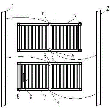
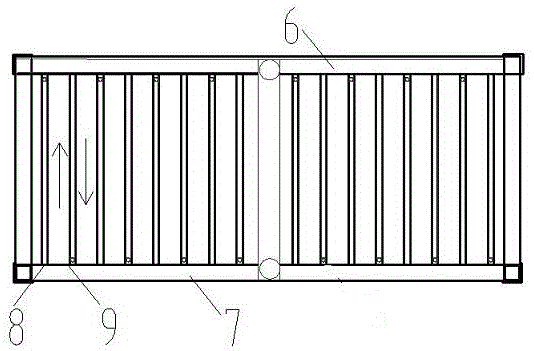
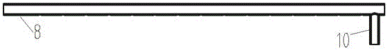
[0022] Such as Figure 1-3 As shown, it includes main aeration pipe one 1, main aeration pipe two 2, at least two sets of membrane racks 3, main aeration pipe one 6 and main aeration pipe two 7 of the membrane rack, and a plurality of branch aeration pipes 8. The main aeration pipe 1 and the main aeration pipe 2 are respectively equipped with electric valves, and the two sides of each set of membrane frames are respectively provided with an air inlet 5 and an air inlet 2 4, and the main aeration pipe 1 and the membrane frame The main aeration pipe 16 is connected through the air inlet 5, the main aeration pipe 2 2 and the main aeration pipe 7 of the membrane frame are connected throu...


PUM

PropertyMeasurementUnit
pore sizeaaaaaaaaaa
heightaaaaaaaaaa

Abstract

The invention discloses a high-efficiency aeration system for a MBR process membrane unit. According to the invention, a main aeration pipeline I and a main aeration pipeline II are separately provided with an electrically operated valve; two sides of each set of membrane rack are respectively provided with an air inlet I and an air inlet II; the main aeration pipeline I is connected with main aeration pipes I of the membrane racks via the air inlets I; the main aeration pipeline II is connected with main aeration pipes II of the membrane racks via the air inlets II; a plurality of branch aeration pipes are arranged to be perpendicular to two main aeration pipes of each set of membrane rack; the air inlets of any two adjacent branch aeration pipes are separately communicated with different main aeration pipes of each set of membrane rack, so staggered inflow of air is realized; the lower surface of each branch aeration pipe is uniformly provided with aeration holes; the lower surface of the tail end of each branch aeration pipe is provided with a sludge-discharging groove; and the total cross-sectional area of aeration holes in each branch aeration pipe is two times greater than the cross-sectional area of the sludge-discharging groove. Through integral designing of the main aeration pipelines and the membrane racks, intermittent aeration of a MBR membrane system is realized, aeration efficiency is improved, membrane contamination is delayed, and the chemical cleaning period of the membrane system is prolonged.

Description

technical field [0001] The invention relates to the technical field of sewage treatment, and more specifically relates to a high-efficiency aeration system used for MBR process membrane units. Background technique [0002] The traditional MBR technology is a gas purging process using continuous aeration, which can generally be designed with an air volume of 3-5m3 / h per curtain. Due to the constant aeration volume and no change in the direction of air bubbles and water flow, the gas purging effect is not good, and even a dead angle of aeration appears. In order to ensure a better gas sweeping effect for the membrane unit, it is necessary to use continuous large-volume aeration to maintain it (close to 5m3 / h). This operation mode leads to very high energy consumption of the membrane system. [0003] With the development of MBR technology, more and more pulse aeration methods are used for MBR gas purging, which improves the aeration efficiency and reduces the aeration energy c...

Claims


Application Information

Patent Timeline
Patent Type & Authority Applications(China)
IPC IPC(8): C02F3/12C02F3/00
CPCC02F3/00C02F3/1268Y02W10/10
Inventor 戴海平杨大为柯永文孙磊刘伟张程
Owner TIANJIN MOTIMO MEMBRANE TECH
Why Eureka
Try Eureka