A stable bucket tooth for an excavator

An excavator and stable technology, which is applied to the field of excavator stable bucket teeth, can solve the problems of easy insertion and inconvenient removal, and achieve the effects of easy insertion and removal, easy operation, and convenient disassembly and installation.

Inactive Publication Date: 2019-08-20
永平县建达鑫鑫合金铸造有限公司
View PDF7 Cites 0 Cited by
  • Summary
  • Abstract
  • Description
  • Claims
  • Application Information

AI Technical Summary

Problems solved by technology

[0004] The invention mainly solves the problem that the pin shaft on the existing bucket teeth is easy to insert but very inconvenient to take out, and provides a stable bucket tooth for excavators that solves the above problems

Method used


Image

  • A stable bucket tooth for an excavator
  • A stable bucket tooth for an excavator
  • A stable bucket tooth for an excavator

Examples


Embodiment 1

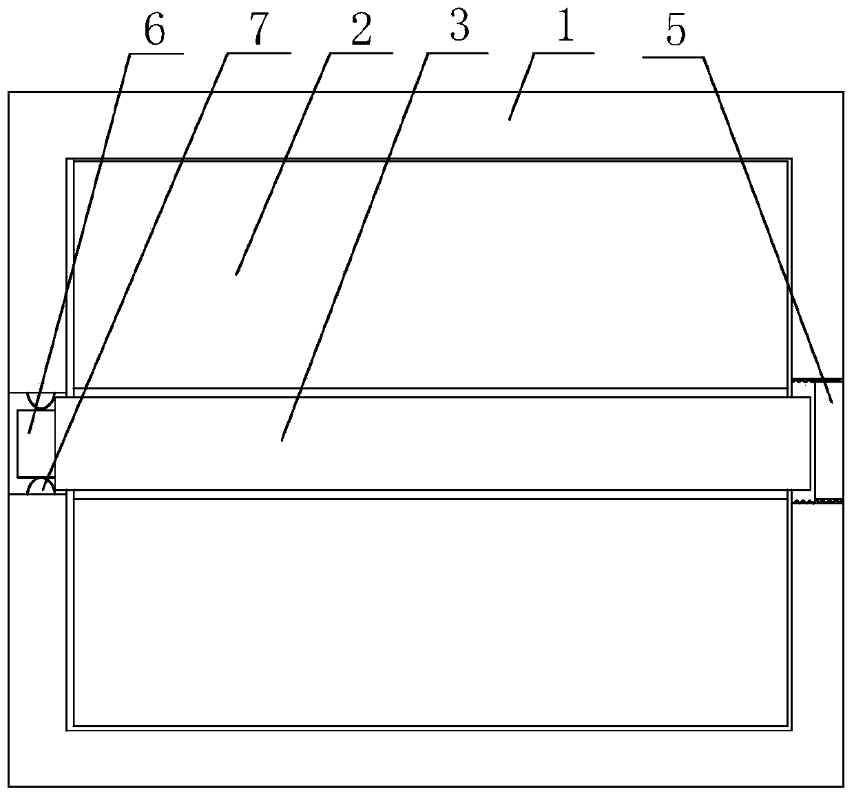
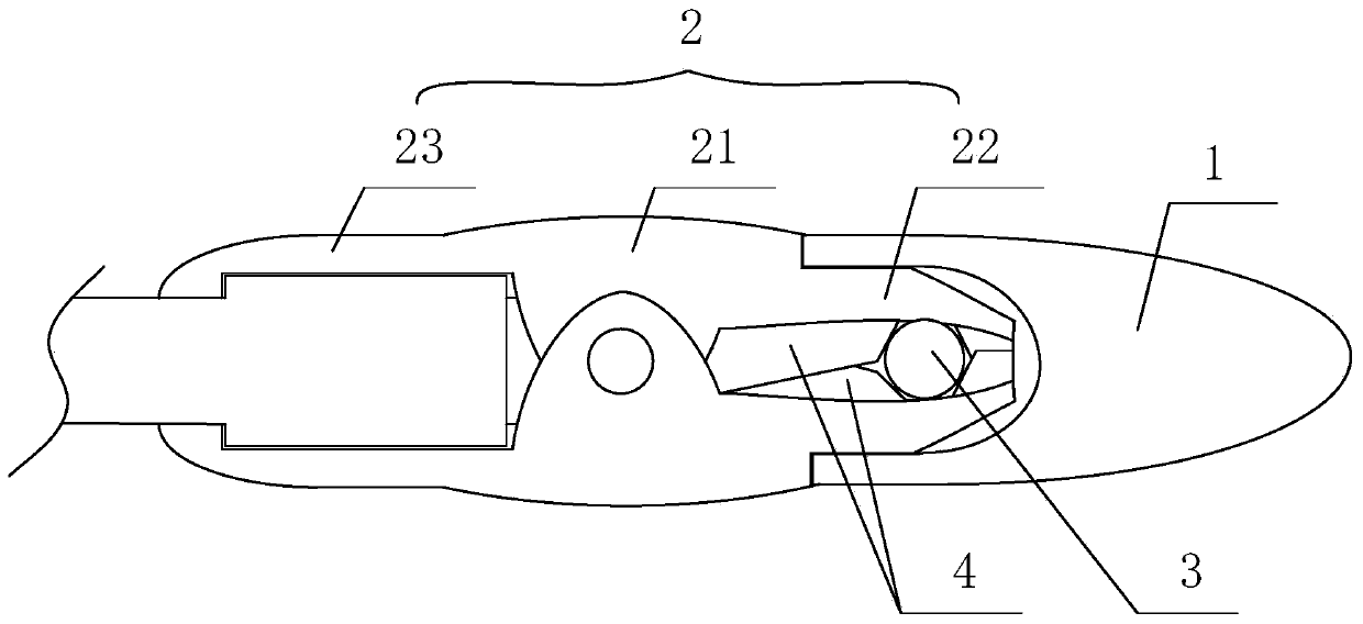
[0035] A stable bucket tooth for an excavator comprises a gear seat 2, a tooth tip 1 with a pin hole, and a pin shaft 3 passing through the pin hole to connect the tooth tip 1 and the tooth seat 2.

[0036] Such as figure 1 As shown, one of the pin shaft holes on the tooth tip 1 is provided with a plugging connector 5, and the pin shaft 3 at one end away from the plugging connector 5 is provided with a slot diameter end 6, and the tooth tip 1 is provided with a The protruding spring part 7 matched with the slot diameter end 6 is screwed with the plugging connecting part 5 and the pin shaft hole.

[0037] In this embodiment, the protruding spring member 7 is composed of a groove arranged on the tip of the tooth, a spring arranged in the groove, and a block fixed on the spring. One end of the block is located in the groove and is fixed with the spring. The other end of the block stretches out of the groove by the elastic force of the spring. The protruding spring part 7 of thi...

Embodiment 2

[0046] The difference between this embodiment and Embodiment 1 is that in this embodiment, the structure between the excavator bucket and the tooth seat 2 is optimized, and the structure between the upper tooth portion and the lower tooth portion is optimized at the same time. The specific settings are as follows:

[0047] The excavator bucket is provided with a protruding part at the connection with the tooth seat 2, and the connection with the excavator bucket on the lower clamping part or / and the upper clamping part is provided with a matching protruding part. groove.

[0048] The upper tooth portion or / and the lower tooth portion are provided with a blocking member 4 that prevents the pin shaft 3 from moving between the upper tooth portion and the lower tooth portion.

[0049] Through the optimization of the above structure, the connection between the excavator bucket and the tooth holder 2 and between the tooth holder 2 and the tooth tip 1 is effectively promoted to be mo...

Embodiment 3

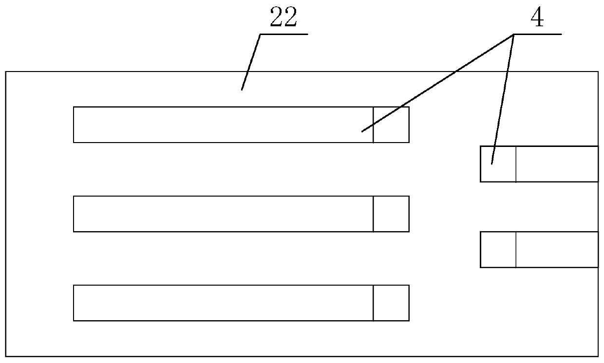
[0051] The difference between this embodiment and Embodiment 2 is that the specific structure of the resistance member 4 is optimized in this embodiment, and the specific settings are as follows:

[0052] There are more than two resistance members 4 , all of which are arranged along a direction perpendicular to the central axis of the pin shaft 3 . In this embodiment, both the upper teeth and the lower teeth are provided with resistance members 4, and the number of upper resistance members 4 on the upper teeth and the lower teeth is respectively set to five, as image 3 shown. In the upper tooth portion, three of the resistance members 4 are arranged on one side of the central axis of the pin shaft 3, and the other two are arranged on the other side of the central axis of the pin shaft 3, such as image 3 shown. Similarly, two stoppers 4 are provided on one side of the lower teeth corresponding to the upper teeth with three stoppers 4, and one side of the lower teeth corresp...


PUM


Abstract

The invention discloses a stable type bucket tooth of an excavator. The problem that a pin shaft of a conventional bucket tooth is simple and convenient to insert but extremely inconvenient to withdraw is solved. The stable type bucket tooth disclosed by the invention comprises a tooth seat (2), a tooth tip (1) with pin shaft holes, and a pin shaft (3) connected with the tooth tip (1) and the tooth seat (2) through the pin shaft holes. The stable type bucket tooth is characterized in that a plugging connecting fitting (5) is arranged at one of the pin shaft holes in the tooth tip (1), a slot diameter end (6) is arranged at one end away from the plugging connecting fitting (5), of the pin shaft (3), and a protruding spring fitting (7) matched with the slot diameter end (6) is arranged on the tooth tip (1). The stable type bucket tooth disclosed by the invention has the advantages of being stable in connection, simple in structure, convenient to disassemble and the like.

Description

technical field [0001] The invention relates to a bucket tooth, in particular to a stable bucket tooth for an excavator. Background technique [0002] At present, most of the bucket teeth on the market are composed of tooth bases and tooth tips connected by pin shafts, and the tooth bases are fixed on the excavator bucket to realize the excavation effect of the excavator bucket. [0003] However, the teeth on the existing excavator buckets need to be connected and disassembled twice to realize the separation and assembly between the tooth seat, the tooth tip and the bucket. Therefore, the installation and replacement of the bucket teeth in the existing structure is very inconvenient, and the pin shaft on the bucket teeth has the problem of being easy to insert but very inconvenient to take out. Contents of the invention [0004] The invention mainly solves the problem that the pin shaft on the existing bucket teeth is easy to insert but very inconvenient to take out, and ...

Claims


Application Information

Patent Timeline
Patent Type & Authority Patents(China)
IPC IPC(8): E02F9/28
Inventor 羊实
Owner 永平县建达鑫鑫合金铸造有限公司
Why Eureka
Try Eureka