A hydraulic control valve

A technology of hydraulic control valve and sliding sleeve, which is applied in the direction of wellbore/well valve device, wellbore/well parts, sealing/packing, etc., which can solve the problem of affecting reliability and service life, and the durability of the electromechanical integrated module of hydraulic control valve. Problems such as safety and stability, to protect the guide pins, improve reliability, and prolong the life of the system

Active Publication Date: 2019-01-11
CHINA NAT OFFSHORE OIL CORP +1
View PDF7 Cites 0 Cited by
  • Summary
  • Abstract
  • Description
  • Claims
  • Application Information

AI Technical Summary

Problems solved by technology

[0003] At present, most of the existing valves still need to be operated by steel wire and cable, and the hydraulic control valves that have been developed are difficult to accurately adjust the opening degree for flow control in deep wells, and the electromechanical integrated module has durability and stability. question
Therefore, the fluid control valve design based on gear position positioning has been proposed, but the current technology only relies on a single guide pin to repeatedly bear all the loads in the form of large shear stress in all directions, and this type of valve needs to be used in extreme underground environments. Long-term service, such a design where the stress points are concentrated in weak positions will seriously affect its reliability and service life

Method used


Image

  • A hydraulic control valve
  • A hydraulic control valve
  • A hydraulic control valve

Examples


Embodiment 1

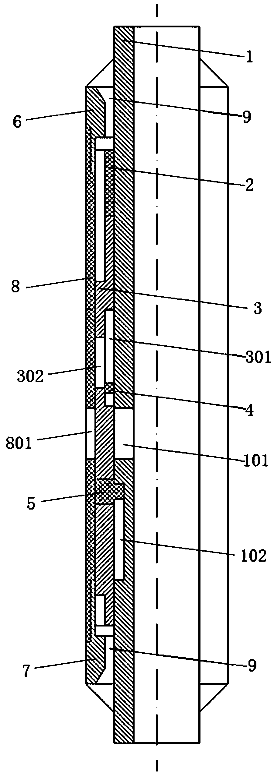
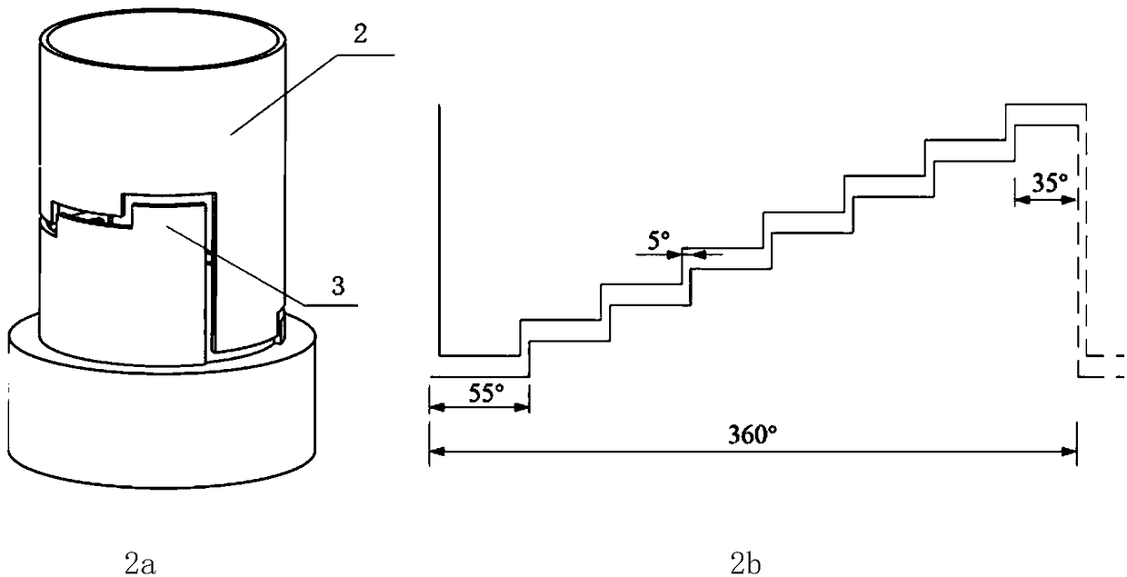
[0030] figure 2 It is an embodiment of the structure corresponding to the upper end of the upper limit structure 2 and the sliding sleeve 3, wherein, the lower end surface of the upper end surface of the upper limit structure 2 and the upper end surface of the helical structure of the sliding sleeve 3 are both set in a stepped shape, and a stepped fit is adopted . figure 2b for figure 2 a The three-dimensional structure is developed along the circumference of the phase coordination diagram, the control valve has eight gears, and the shifting action of the sliding sleeve 3 is roughly divided into the following three steps:

[0031] (1) Inject liquid into the interior through the hydraulic pipeline 9, drive the sliding sleeve 3 to move downward, and the upper helical structure of the sliding sleeve 3 is completely disengaged from the upper limit structure 2 (that is, the stepped helical structure at the upper end of the sliding sleeve 3 rotates around the axis During the mo...

Embodiment 2

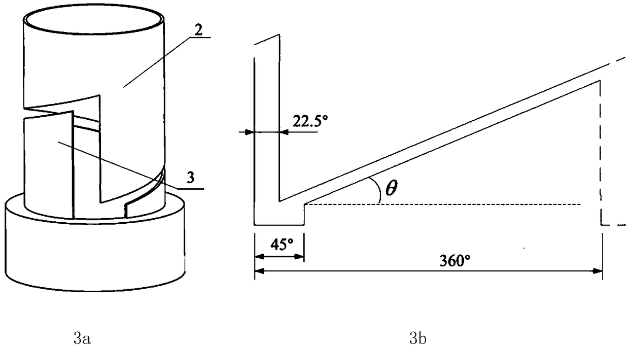
[0036] image 3 It is another embodiment of the structure corresponding to the upper end of the upper limit structure 2 and the sliding sleeve 3, wherein, the lower end surface of the upper limit structure 2 helical structure and the upper end surface of the sliding sleeve 3 helical structure are set as planar, and the spiral plane type is adopted. cooperation. image 3 b for image 3 a The phase coordination diagram of the three-dimensional structure developed along the circumference, and the control valve has eight gears.

[0037] In order to avoid jamming during the shifting action and affect the reliability of the system, the helical planar fit is also set with a 45° "non-contact phase". Compared with the stepped fit, the continuously changing spiral planar fit is easier to process and fine-tune the system, but because the limit structure needs to resist the rotational movement of the sliding sleeve 3 relative to the central tube 1 while bearing the axial force, so When...


PUM


Abstract

The invention discloses a hydraulic control valve comprising a central pipe. An inner through hole and a guiding groove are formed in the side wall of the central pipe. The central pipe is successively sleeved with an upper end connector, an upper limiting structure, a sliding sleeve and a lower end connector from top to bottom; the upper end connector and the lower end connector both are provided with axial hydraulic pipelines; the sliding sleeve is sleeved with a shell body; the upper and lower ends of the shell body are connected with the upper end connector and the lower end connector correspondingly; an outer through hole is formed in the side wall of the shell body; an annular groove is formed in the inner wall of the sliding sleeve; a communicating hole communicating with the annular groove is formed in the side wall of the sliding sleeve; a guiding pin sliding along the guiding groove is arranged on the side wall of the sliding sleeve; the central pipe is sleeved with a lower limiting structure; and the lower limiting structure is located in the annular groove of the inner wall of the sliding sleeve. The flow of conveying liquid can be adjusted accurately just through hydraulic control, meanwhile, the situation that weak components are protected can be guaranteed, and the service life of equipment is prolonged.

Description

technical field [0001] The invention belongs to the technical field of petroleum engineering well completion, in particular to a hydraulic control valve. Background technique [0002] At present, it is difficult to operate horizontal wells, branch wells, and extended-reach deep wells in offshore oilfields. Conventional steel wire, cable, and coiled tubing operations cannot meet the requirements for injection-production control of horizontal wells and highly-inclined wells. Injection-production, downhole production dynamics cannot be adjusted in real time, and cannot meet the needs of efficient injection-production development of reservoirs; conventional technology layered injection-production wells need to be run into pipe strings or steel wires, cables, and coiled tubing operations, which are low in efficiency, high in cost, and high in risk ; During the long-term injection-production process, changes in formation parameters require dynamic adjustment of injection-productio...

Claims


Application Information

Patent Timeline
Patent Type & Authority Patents(China)
IPC IPC(8): E21B34/08
CPCE21B34/08
Inventor 王立苹张凤辉刘佳君马认琦杨万有程心平张玺亮
Owner CHINA NAT OFFSHORE OIL CORP
Why Eureka
Try Eureka