Eureka AIR delivers breakthrough ideas for toughest innovation challenges, trusted by R&D personnel around the world.

Dehumidifying mechanism

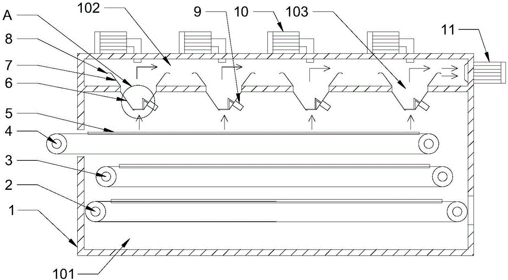
A wet wind and wet hood technology is applied in the field of medicinal material drying equipment, which can solve the problems of incomplete dehumidification by a dehumidifying device, incomplete drying of medicinal materials, and difficulty in controlling the quality of dried finished products, so as to avoid incomplete dehumidification, simple structure, and exhaustion. Wet efficient effect

Inactive Publication Date: 2017-05-10
天津市格亚思科技发展有限公司
View PDF0 Cites 0 Cited by
  • Summary
  • Abstract
  • Description
  • Claims
  • Application Information

AI Technical Summary

Problems solved by technology

[0002] As we all know, the purpose of using a drying device in the pharmaceutical industry is to remove some raw materials, moisture or solvents in semi-finished products, so as to improve product quality, facilitate material processing, use, and facilitate transportation and storage. Existing drying boxes generally include material conveying Belt, heating and drying device and dehumidification device, but the dehumidification device of the existing equipment generally has problems such as incomplete dehumidification, resulting in incomplete drying of medicinal materials and difficulty in controlling the quality of dried products.

Method used


Image

  • Dehumidifying mechanism
  • Dehumidifying mechanism

Examples


Embodiment Construction

[0021] It should be noted that, in the case of no conflict, the embodiments of the present invention and the features in the embodiments can be combined with each other.

[0022] In describing the present invention, it should be understood that the terms "center", "longitudinal", "transverse", "upper", "lower", "front", "rear", "left", "right", The orientations or positional relationships indicated by "vertical", "horizontal", "top", "bottom", "inner", "outer", etc. are based on the orientation or positional relationships shown in the drawings, and are only for the convenience of describing the present invention Creation and simplification of description, rather than indicating or implying that the device or element referred to must have a specific orientation, be constructed and operate in a specific orientation, and therefore should not be construed as limiting the invention. In addition, the terms "first", "second", etc. are used for descriptive purposes only, and should no...


PUM


Abstract

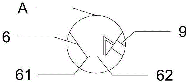
The invention provides a dehumidifying mechanism. Air deflectors are fixedly connected to the two sides of each moisture discharging port in a dehumidifying air flue. Every two air deflectors are in a horn mouth shape. One side of each air deflector is fixedly connected to the bottom face of the dehumidifying air flue, and the other side of each air deflector is fixedly connected with an air guiding bent plate. An auxiliary dehumidifying motor is arranged above each moisture discharging port in the dehumidifying air flue. A main dehumidifying motor is arranged at one end of the dehumidifying air flue. The dehumidifying mechanism is simple in structure and is provided with the air deflectors and the air guiding bent plates, the corresponding auxiliary dehumidifying motor is arranged above each moisture discharging port and sucks moisture up, the wind with the moisture is guided to move towards the position above the dehumidifying air flue through the air deflectors, the wind sucking negative pressure of the main dehumidifying motor is larger than that of each auxiliary dehumidifying motor, and the main dehumidifying motor sucks wind in the dehumidifying air flue away.

Description

technical field [0001] The invention belongs to the technical field of medicinal material drying equipment, and in particular relates to a dehumidification mechanism. Background technique [0002] As we all know, the purpose of using a drying device in the pharmaceutical industry is to remove some raw materials, moisture or solvents in semi-finished products, so as to improve product quality, facilitate material processing, use, and facilitate transportation and storage. Existing drying boxes generally include material conveying Belt, heating and drying device and dehumidification device, but the dehumidification device of the existing equipment generally has problems such as incomplete dehumidification, resulting in incomplete drying of medicinal materials, and difficult control of the quality of dried products. Contents of the invention [0003] In view of this, the present invention aims to propose a dehumidification mechanism to improve the dehumidification effect, inc...

Claims


Application Information

Patent Timeline
IPC IPC(8): F26B15/18F26B25/00
CPCF26B15/18F26B25/005
Inventor 周玉臣
Owner 天津市格亚思科技发展有限公司
Why Eureka
Eureka Blog
Learn More