Flexible leg launch adjustment mechanism

A launch adjustment and flexible leg technology, applied in the testing of machines/structural components, vehicle testing, instruments, etc., can solve problems such as joint deformation, inability to guide flexible legs, and inability to reach the collision position

Active Publication Date: 2020-07-24
ZHEJIANG GEELY HLDG GRP CO LTD +1
View PDF9 Cites 0 Cited by
  • Summary
  • Abstract
  • Description
  • Claims
  • Application Information

AI Technical Summary

Problems solved by technology

However, the existing rigid leg launch adjustment frame cannot be used for flexible legs, such as the flexible legs of the Flex-PLI leg type. The Flex-PLI leg type is composed of the femur, tibia and the knee connecting the femur and tibia. The femur consists of 8 joints The tibia is composed of 10 joints, the knee is composed of upper and lower parts and 12 steel cables; the front of the femur and tibia of the Flex-PLI leg type is flat, while the knee protrudes outward, and the back of the Flex-PLI leg type for plane
When using the existing rigid leg launch adjustment frame to place the Flex-PLI leg for the back impact test (the front of the Flex-PLI leg abuts against the push slot of the rigid leg launch adjustment frame), due to the flex-PLI leg protrudes and leans against the push groove, while at least one end of the femur or tibia of the Flex-PLI leg is suspended, the push groove cannot support the femur or the tibia at the same time, and when the launching device accelerates and pushes the Flex-PLI leg, it is easy to cause The condyle of the femur or tibia is deformed after the Flex-PLI leg type flies out, which cannot meet the induction value requirements of the pre-collision regulations on the bending moment of the tibial condyle
Moreover, the existing rigid leg launch adjustment frame cannot guide the flexible leg, cannot correct the flight trajectory of the flexible leg, and cannot reach the ideal collision position

Method used


Image

  • Flexible leg launch adjustment mechanism
  • Flexible leg launch adjustment mechanism
  • Flexible leg launch adjustment mechanism

Examples


Embodiment Construction

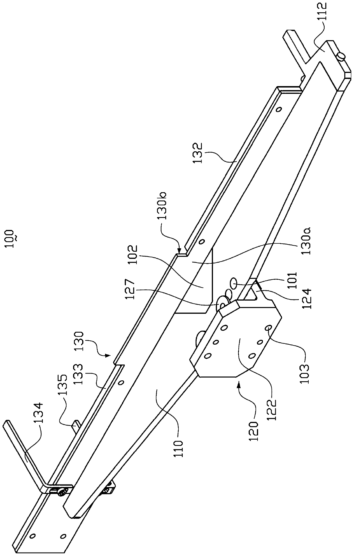
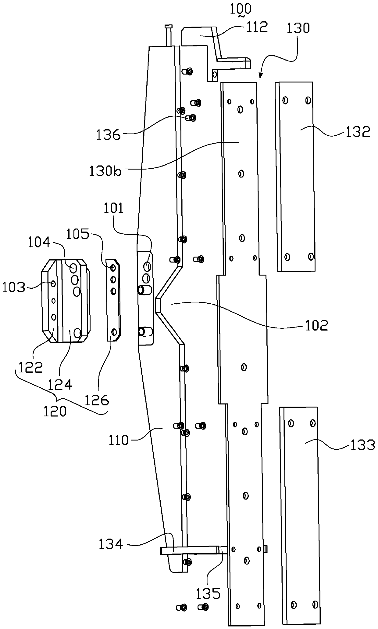
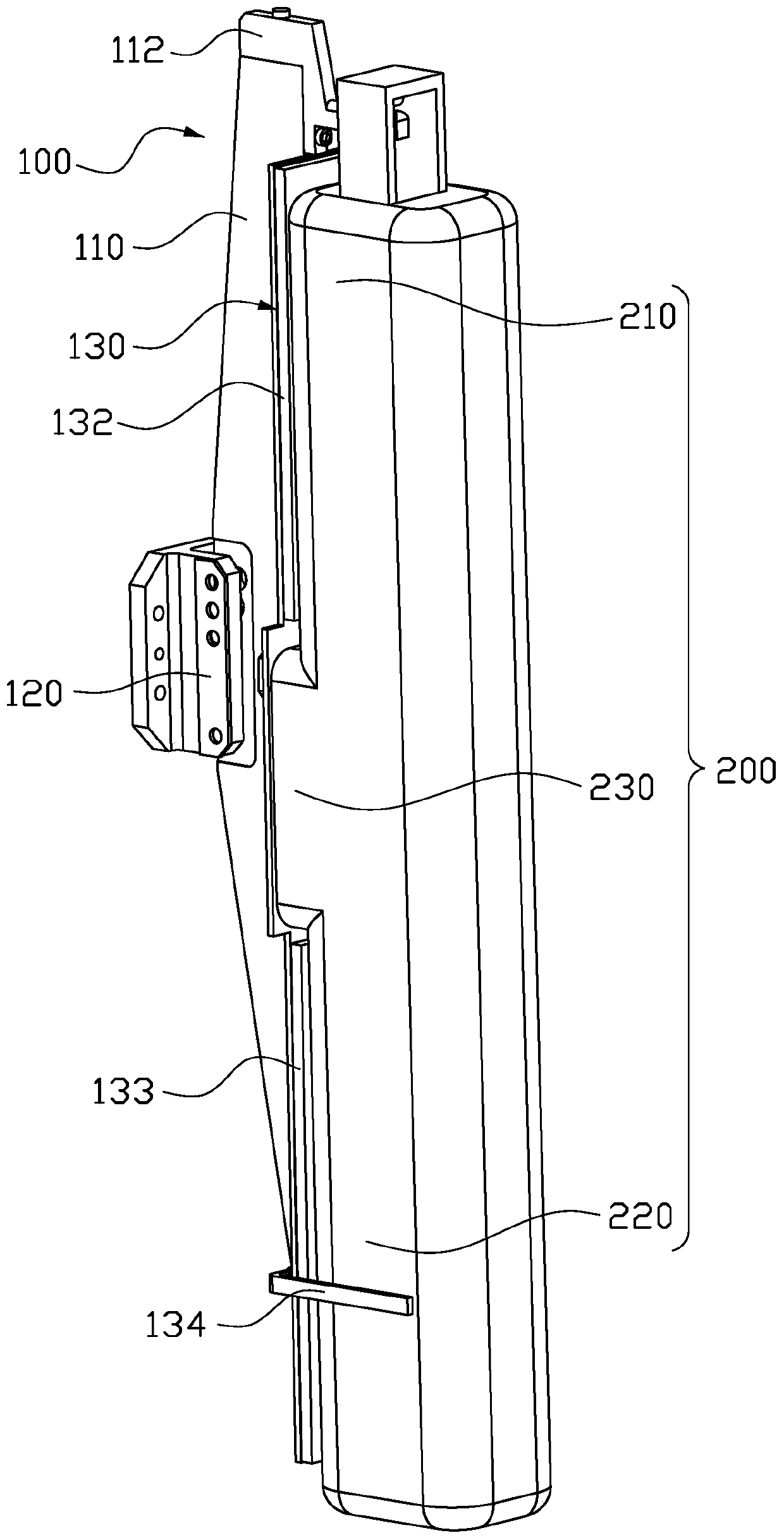
[0022] In order to further explain the technical means and effects that the present invention takes to achieve the intended purpose of the invention, below in conjunction with the accompanying drawings and preferred embodiments, the specific implementation, structure, characteristics and features of the flexible leg emission adjustment mechanism proposed according to the present invention will be described below. Efficacy, detailed as follows:

[0023] The aforementioned and other technical contents, features and effects of the present invention will be clearly presented in the following detailed description of preferred embodiments with reference to the drawings. Through the description of specific implementation methods, the technical means and effects of the present invention to achieve the intended purpose can be understood more deeply and specifically, but the attached drawings are only for reference and description, and are not used to explain the present invention limit...


PUM


Abstract

The invention provides an emission adjusting mechanism of a flexible leg. The mechanism is composed of a support plate, a fixed plate, and a baffle plate. The support plate is arranged between the fixed plate and the baffle plate; and the two sides of the support plate are connected with the fixed plate and the baffle plate respectively. The baffle plate has a first mounting surface and a second mounting surface opposite to the first mounting surface; the support plate is connected to the first mounting surface of the baffle plate; and the second mounting surface of the baffle plate is used for placing a first buffer plate and a second buffer plate of a flexible leg, wherein the first buffer plate and the second buffer plate are opposite to each other. According to the adjusting mechanism, a thighbone and a shin bone of a flexible leg can be supported well and thus deformation of the thighbone, the shin bone and the knee due to emission of the flexible leg can be avoided. And the sensing value of the flexible leg during the flight process can meet the regulatory requirement.

Description

technical field [0001] The invention relates to the technical field of testing devices, in particular to a flexible leg launch adjustment mechanism. Background technique [0002] With the development of society and the improvement of people's living standards, automobiles have gradually become the main means of transportation for people to travel, and more and more attention has been paid to the safety performance of automobiles. In the field of automobile safety research, pedestrian protection is a very important component, and the design of pedestrian protection is related to the shape, layout and structure of the front end of the vehicle. Pedestrians are vulnerable groups in traffic. Once an accident occurs, the legs of pedestrians are one of the most vulnerable parts. [0003] In the case of a lower body collision between a car and a pedestrian, the combination of the collision force and possible axial torque on the leg can result in a multiplied injury, with shear forc...

Claims


Application Information

Patent Timeline
Patent Type & Authority Patents(China)
IPC IPC(8): G01M17/007
CPCG01M17/0078
Inventor 郑佳丽王章平张毅
Owner ZHEJIANG GEELY HLDG GRP CO LTD
Why Eureka
Try Eureka