Rock-like material tension-shear and biaxial tension-compression testing device and use method thereof

A test device, rock technology, applied in the field of rock and soil mechanics, to achieve the effect of easy control, simple operation and simple structure

Active Publication Date: 2017-05-10
HEBEI UNIV OF TECH
View PDF6 Cites 11 Cited by
  • Summary
  • Abstract
  • Description
  • Claims
  • Application Information

AI Technical Summary

Problems solved by technology

[0004] The object of the present invention is to provide a test device and method for tensile-shear test and biaxial tensile-compression test of rock materials with simple structure and accurate test results, so as to solve the defects of the existing technology in economy and practicability, and realize the test in the biaxial test. Tensile-shear tests and biaxial tension-compression tests on axial testing machines

Method used


Image

  • Rock-like material tension-shear and biaxial tension-compression testing device and use method thereof
  • Rock-like material tension-shear and biaxial tension-compression testing device and use method thereof
  • Rock-like material tension-shear and biaxial tension-compression testing device and use method thereof

Examples


Embodiment 1

[0061] This embodiment discloses a rock material tension-shear and biaxial tension-compression test device, including frame I1, frame II2, upper platen 3, slider I4, slider II40, backing plate 6, testing machine loading head I91, testing machine Loading head II92, testing machine loading head III93 and testing machine loading head IV94.

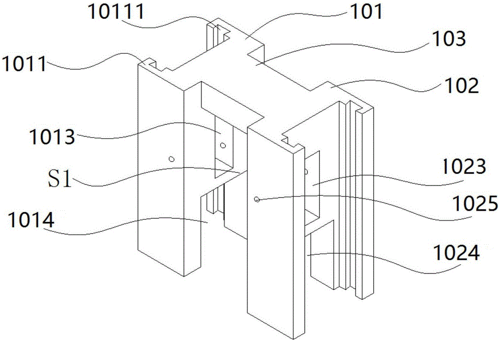
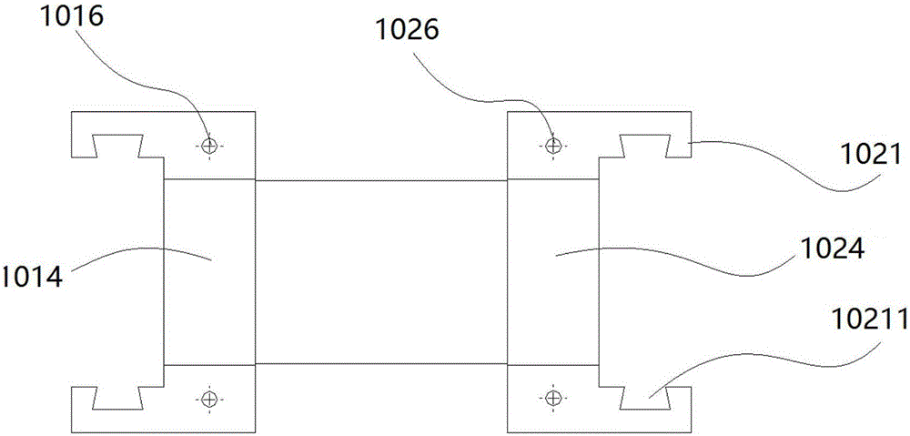
[0062] see image 3 and Figure 4 , the frame I1 includes a column I101, a column II102 and a beam I103. The beam I 103 is connected between the column I 101 and the column II 102, and the bottom surfaces of the three are flush. The column I101, column II102 and beam I103 enclose a semi-enclosed space IS1. The column I101, column II102 and beam I103 enclose shape. The column I 101, the column II 102 and the beam I 103 are integrated.

[0063] A cuboid A is removed from the bottom surface of the column I101 to form a gap I1014. The gap I1014 runs through both sides of the column I101. An outlet of the notch I1014 is in the semi-enclos...

Embodiment 2

[0083] This embodiment discloses a biaxial tension-compression test method using the rock material tension-shear and biaxial tension-compression test device described in Embodiment 1, comprising the following steps:

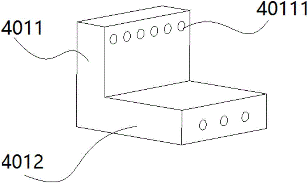
[0084] 1) Align the right-angle plate I401 and the right-angle plate II4001 with the sample 8, and use superglue to paste the horizontal plate I4012 and the horizontal plate II40012 respectively on the upper and lower surfaces of the sample 8 to form an assembly.

[0085] 2) After the superglue is completely solidified, place the assembly in the space IS. Install the slider I4 and the slider II40 on the beam I103 and the beam II203 respectively: install the roller shaft I404 first, and then connect the right-angle plate I401 and the side plate I402 with bolts and reducing bolts I403. Install the roller shaft II4004 first, and then connect the right-angle plate II4001 and the side plate II4002 with bolts and reducing bolts II4003.

[0086] 3) Install side pressur...

Embodiment 3

[0090] This embodiment discloses a tensile-shear test method using the rock material tensile-shear and biaxial tensile-compression test device described in Embodiment 1, comprising the following steps:

[0091] 1) Align the right-angle plate I (401) and right-angle plate II (4001) with the sample (8), and use super glue to paste the horizontal plate I (4012) and the horizontal plate II (40012) on the upper and lower surfaces of the sample (8). , forming an assembly;

[0092] 2) After the superglue is completely solidified, place the assembly in space I (S); install slider I (4) and slider II (40) on beam I (103) and beam II (203) respectively : Install the roller shaft I (404) first, then connect the right-angle plate I (401) and the side plate I (402) with bolts and reducing bolts I (403); install the roller shaft II (4004) first, then use bolts and variable diameter bolts The diameter bolt II (4003) connects the right-angle plate II (4001) and the side plate II (4002);

[...


PUM


Abstract

The invention provides a rock-like material tension-shear and biaxial tension-compression testing device and a use method thereof. The device comprises a frame I, a frame II, an upper pressing plate, a pull head I, a pull head II, a base plate, a tester loading head I, a tester loading head II, a tester loading head III and a tester loading head IV; the frame II can move along a vertical direction to convert vertical pressure of a tester into tension; a sample freely deforms in a horizontal pressure direction. The device is simple in structure, a test result is accurate, the aims of performing a tension-shear test and a biaxial tension-compression test on a biaxial tester can be achieved, and the test cost is greatly lowered.

Description

technical field [0001] The invention relates to the field of rock and soil mechanics, in particular to a device and method for performing tensile-shear tests and biaxial tension-compression tests on rock materials. Background technique [0002] Under natural conditions, the underground rock mass is usually in a three-dimensional compression state under the action of self-weight stress and structural stress. Transition to a bidirectional or even unidirectional stress state. At the same time, the excavation of the rock mass causes the surrounding rock mass to produce a strong unloading effect, which in turn causes the rebound deformation and bending deformation of the rock mass, which will inevitably cause the rock mass to generate tensile stress within a certain range. In addition, complex stress states such as tension, tension-shear, tension-compression and corresponding rock mass failure will occur in the rock slope unloading zone, rock mass near faults, and earthquake epi...

Claims


Application Information

Patent Timeline
Patent Type & Authority Applications(China)
IPC IPC(8): G01N3/08G01N3/24G01N3/02
CPCG01N3/02G01N3/08G01N3/24G01N2203/0003G01N2203/0016G01N2203/0023G01N2203/0067G01N2203/0254
Inventor 黄达朱谭谭岑夺丰曾彬宋宜祥
Owner HEBEI UNIV OF TECH
Why Eureka
Try Eureka