Automatic detection system and automatic detection method for workpiece defects

An automatic detection and workpiece technology, applied in the direction of optical testing flaws/defects, measuring devices, material analysis through optical means, etc., can solve the problems of complex digital image acquisition and low degree of automation, and achieve the effect of automatic detection

Pending Publication Date: 2017-05-10
HUBEI BUSINESS COLLEGE
View PDF11 Cites 17 Cited by
  • Summary
  • Abstract
  • Description
  • Claims
  • Application Information

AI Technical Summary

Problems solved by technology

However, for workpieces such as shaft holes, the detection of internal defects of the workpiece is also an indispensable link in industrial production. However, du

Method used


Image

  • Automatic detection system and automatic detection method for workpiece defects
  • Automatic detection system and automatic detection method for workpiece defects
  • Automatic detection system and automatic detection method for workpiece defects

Examples


Embodiment 8

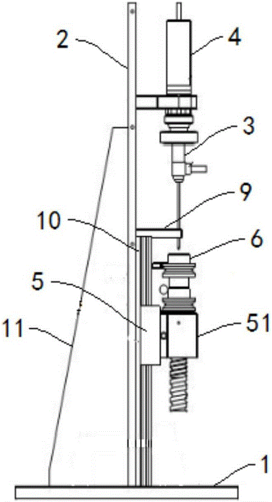
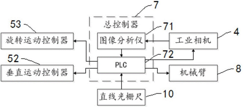
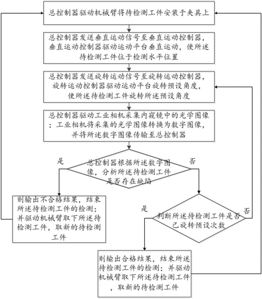
[0072] The method for automatic detection of workpiece defects described in Embodiment 8 of the present invention, on the basis of Embodiment 7, the general controller 7 includes an image analyzer 71 and a PLC 72;

[0073] The further concrete realization of described step 2 comprises the following steps:

[0074] Step b21, PLC72 sends a vertical motion signal to the vertical motion controller 52, and the vertical motion controller 52 drives the motion platform 5 to move vertically;

[0075] Step b22, the linear grating ruler 10 detects the position coordinates of the workpiece 6 to be detected, and transmits the position coordinates to the PLC72;

[0076] In step b23, the PLC 72 compares the position coordinates with the detected horizontal position coordinates, and if the error is smaller than the preset value, then execute step 3; otherwise, return to execute step b21.

Embodiment 9

[0077] The method for automatic detection of workpiece defects described in Embodiment 9 of the present invention, on the basis of Embodiment 6, the general controller 7 includes an image analyzer 71 and a PLC 72;

[0078] The specific implementation of the step 3 is that the PLC72 sends a rotation motion signal to the rotation motion controller 53, and the rotation motion controller 53 drives the motion platform 5 to rotate a preset angle, so that the workpiece 6 to be detected rotates the preset angle;

[0079] The step 4 is specifically implemented as PLC72 drives the industrial camera 4 to collect the optical image in the endoscope 3; the industrial camera 4 converts the collected optical image into a digital image, and transmits the digital image to the image analyzer 71;

[0080] The step 5 is specifically implemented as the image analyzer 71 receiving the digital image, and analyzing whether there is a defect in the workpiece 6 to be detected according to the digital ima...

Embodiment 11

[0087] The method for automatic detection of workpiece defects described in Embodiment 11 of the present invention, on the basis of Embodiment 10,

[0088] The step S1 is specifically realized by performing brightness non-uniformity correction on the digital image by using a frequency domain homomorphic filtering operation to obtain a brightness corrected image.

[0089] According to the illumination reflection model, the digital image is represented by the following first formula;

[0090] The first formula is as follows:

[0091] f(x,y)=i(x,y)r(x,y)

[0092] Wherein, the f (x, y) is the light intensity of the digital image, the i (x, y) is the incident component of the light intensity of the digital image, and the r (x, y) is the reflection component of the light intensity of the digital image;

[0093] According to the following second formula, the digital image is corrected for brightness non-uniformity by using a frequency-domain homomorphic filtering operation to obtai...


PUM


Abstract

The invention relates to an automatic detection system and an automatic detection method for workpiece defects. The automatic detection system comprises a base, wherein a linear guide rail is vertically arranged on the base; an endoscope is fixedly arranged at the other end, opposite to the base, of the liner guide rail, and is externally connected with an industrial camera; a moving platform is arranged at a position, positioned between the endoscope and the base, on the linear guide rail; a clamp for clamping a to-be-detected workpiece is arranged on the moving platform; the moving platform also comprises a vertical motion controller and a rotary motion controller; the system also comprises a master controller and a mechanical arm; the master controller is electrically connected with the industrial camera, the vertical motion controller, the rotary motion controller and the mechanical arm. The automatic detection system and the automatic detection method disclosed by the invention have the beneficial effect that automatic detection on internal defects in the to-be-detected workpiece is realized.

Description

technical field [0001] The invention relates to the technical field of workpiece defect detection, in particular to an automatic detection system and method for workpiece defects. Background technique [0002] The area array industrial camera can directly acquire the digital image of the surface of the workpiece, and then realize the detection of the surface defects of the workpiece. At present, the surface defects of the workpiece can be automatically detected. However, for workpieces such as shaft holes, the detection of internal defects of the workpiece is also an indispensable link in industrial production. However, due to the complexity of acquiring digital images inside the workpiece, the degree of automation for internal defect detection of workpieces is not high at present. Contents of the invention [0003] The purpose of the present invention is to provide a workpiece defect automatic detection system and method to solve the above-mentioned problems existing in t...

Claims


Application Information

Patent Timeline
IPC IPC(8): G01N21/88
CPCG01N21/8851
Inventor 鞠剑平马聪徐志聪杨国庆郑朝晖林明玉吕毅
Owner HUBEI BUSINESS COLLEGE
Why Eureka
Try Eureka