
L-shaped impedance matching network design method

A technology of impedance matching network and design method, which is applied in the direction of CAD circuit design, calculation, special data processing application, etc., can solve the problems of complex steps, time-consuming, low success rate, etc., to simplify the design method, avoid manual calculation and repetition The effects of experiments and design time saving

Inactive Publication Date: 2017-05-10
XIAN HUAXUN MICROELECTRONICS
View PDF4 Cites 1 Cited by
  • Summary
  • Abstract
  • Description
  • Claims
  • Application Information

AI Technical Summary

Problems solved by technology

[0008] The purpose of the present invention is to provide a method for designing an L-type impedance matching network to solve the problems of complex steps, time-consuming, and low success rate of the existing L-type impedance network design method

Method used


Image

  • L-shaped impedance matching network design method
  • L-shaped impedance matching network design method
  • L-shaped impedance matching network design method

Examples


Embodiment Construction

[0033] The present invention will be described in detail below in conjunction with the accompanying drawings and specific embodiments.

[0034] The invention discloses a method for designing an L-shaped impedance matching network, which comprises the following steps:

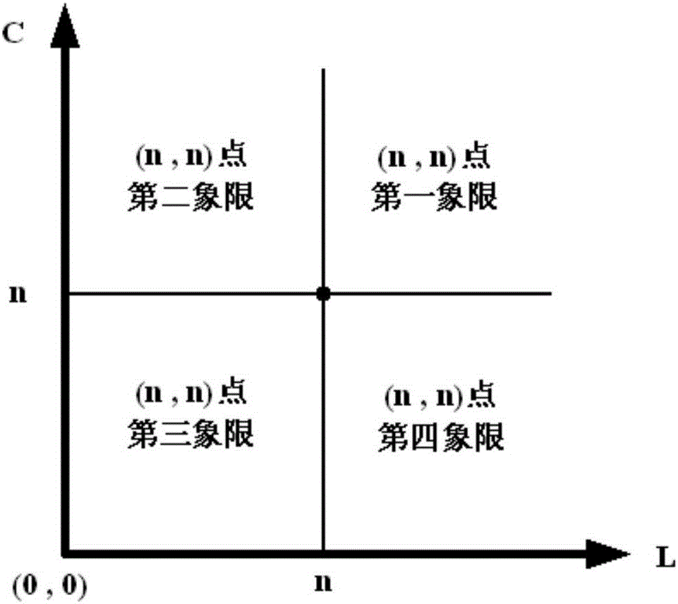
[0035] Step 1. Establish a two-dimensional impedance plane, and establish a two-dimensional impedance plane coordinate system in the plane. The horizontal axis is the inductance axis, indicating the inductance value in the L-type impedance matching network, and the vertical axis is the capacitance axis, indicating the L-type impedance matching. The capacitance value in the network, any point in the plane represents the inductance value and capacitance value in the L-type impedance matching network, assuming that the design of the L-type impedance matching network is successful, then there must be a point corresponding to it in this two-dimensional impedance plane, and is unique, therefore, the design work of the...


PUM


Abstract

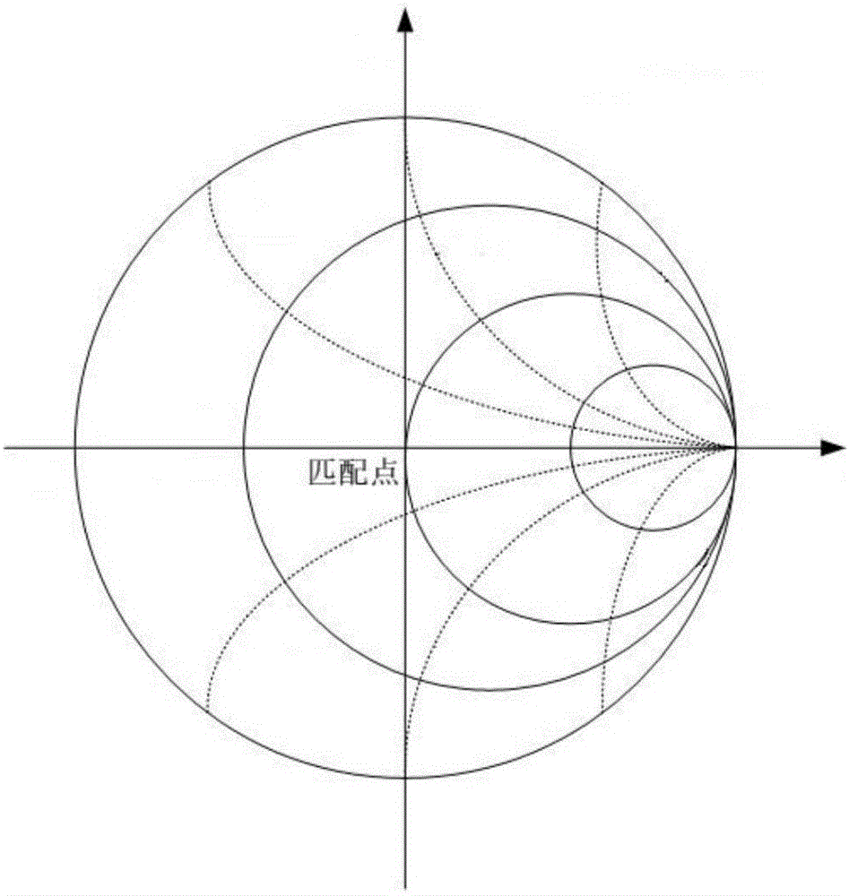
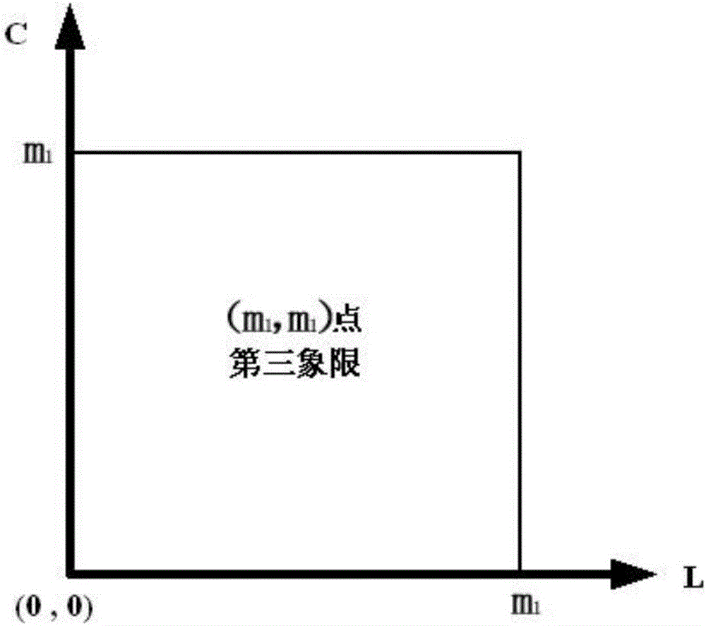
The invention discloses an L-shaped impedance matching network design method, comprising the steps of establishing a two-dimensional impedance plane and selecting a starting point in the two-dimensional impedance plane; designing an L-shaped impedance matching network according to the starting point, and measuring a characteristic impedance value Z (n, n), then judging whether the starting point is the matching point, and if so, designing the L-shaped impedance matching network according to the matching point; otherwise, continuing to implement; increasing capacitance and inductance values corresponding to the starting point, and measuring a corresponding characteristic impedance value Z (m, m); continuing to implement when Z (m, m) is closer to the center of the graph than Z (n, n), otherwise re-selecting; increasing the corresponding capacitance and inductance values, and judging that the matching point is located in the third quadrant of the impedance plane at the previous point of the point when the distance between Z (m, m) and the center of the original image of the Smith is larger than the starting distance; and reducing the range of the matching point to obtain a final matching region, and designing the L-shaped impedance matching network.

Description

[0001] 【Technical field】 [0002] The invention belongs to the field of radio frequency circuit design, in particular to an L-shaped impedance matching network design method. [0003] 【Background technique】 [0004] Impedance matching is a very important concept in radio frequency circuits. Only when the input impedance of the circuit driven by the signal source is conjugate to the signal source impedance, the power absorbed by the circuit from the signal source can reach the maximum value, which is called signal source driven. The circuit has reached the input impedance matching condition. In order to meet the impedance matching conditions and maximize the transmission power, it is often necessary to transform a certain impedance (source impedance) to another specific impedance (load impedance). The circuit that realizes this function is an impedance matching network. At present, there are many kinds of networks that can realize the impedance matching function. Among them, th...

Claims


Application Information

Patent Timeline
Patent Type & Authority Applications(China)
IPC IPC(8): G06F17/50
CPCG06F30/36
Inventor 申向顺周文益
Owner XIAN HUAXUN MICROELECTRONICS
Learn More