Synthesis method of array antenna shaped beam with controllable excitation amplitude dynamic range

A technology of excitation amplitude and dynamic range, applied to antennas, antenna arrays, instruments, etc., can solve the problems of no excitation amplitude dynamic range control, no consideration of the influence of array element mutual coupling effect, etc., and achieve high universality

Active Publication Date: 2017-05-10
XIAMEN UNIV +1
View PDF6 Cites 15 Cited by
  • Summary
  • Abstract
  • Description
  • Claims
  • Application Information

AI Technical Summary

Problems solved by technology

[0006] The shaped beam synthesis methods involved in the first two patents mentioned above do not consider the influence of the mutual coupling effect between array elements. Although the third article considers the mutual coupling effect, it only discusses the linear array; on the other hand, none of the above patents Control over the dynamic range of excitation amplitude

Method used


Image

  • Synthesis method of array antenna shaped beam with controllable excitation amplitude dynamic range
  • Synthesis method of array antenna shaped beam with controllable excitation amplitude dynamic range
  • Synthesis method of array antenna shaped beam with controllable excitation amplitude dynamic range

Examples


Embodiment 1

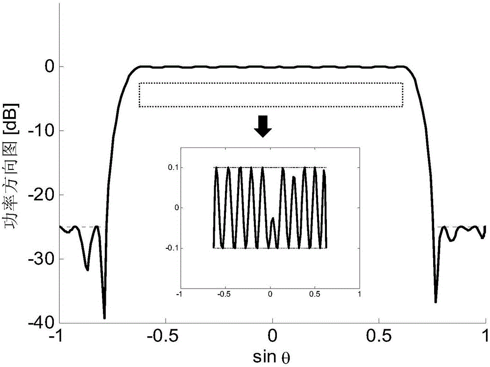
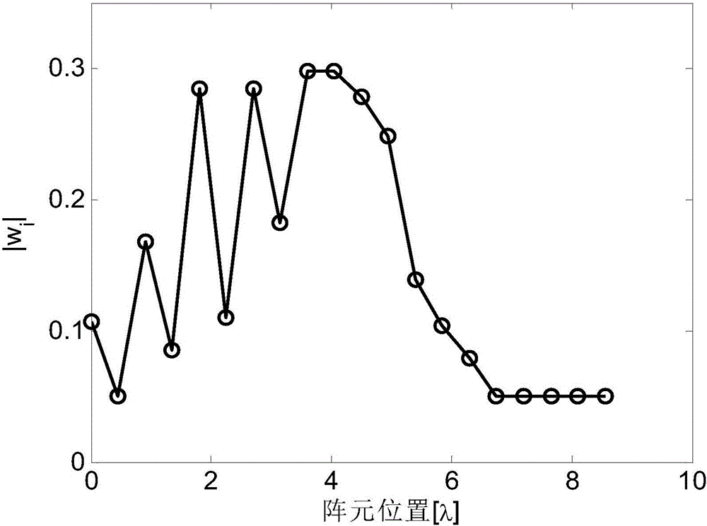
[0071] The validity of the method is verified by referring to the flat-top pattern synthesis example in [1]. Consider a 20-element uniform linear array composed of ideal point sources, the array element spacing is d=0.45λ, and the constraints are: within the shaped area |θ|≤40°, the fluctuation range of the pattern is ±0.1dB; the side lobe In the region |θ|≥50°, the upper boundary level of the pattern is lower than -25dB. Literature [1] does not constrain the excitation amplitude, and from the excitation distribution of literature [1] figure 1 It can be seen from (b) that the dynamic amplitude range ratio is close to DRR at this time max =60. Now, the method proposed by the present invention is used to synthesize the shaped power pattern under the control of the dynamic range of the excitation amplitude, where DRR is set max = 6, the integrated power pattern is as follows figure 1 As shown, the pattern of the shaped area and the side lobe area all meet the constraints in t...

Embodiment 2

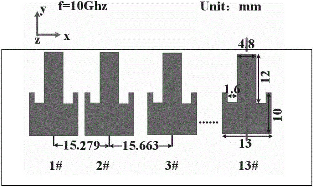
[0073] In order to further verify that the method proposed by the present invention is also applicable to non-uniform arrays considering coupling, this example will use the non-uniform linear array cosecant pattern synthesis example in document [2] as a comparison. Literature [2] is aimed at the ideal point source when performing array synthesis, and does not consider the influence of mutual coupling effect between array elements.

[0074] image 3 A 13-element non-uniform linear array model based on full-wave simulation software is given. It is assumed that the element antenna is a microstrip antenna with a working frequency of 10GHz. The dielectric plate is Rogers 5880 with a thickness of 1.575mm. The dimensions of the antenna element are shown in Fig.[ 3], and the position of the array element is obtained from Table 2 in the literature [2]. In this example, the constraints to be satisfied by the integrated pattern are: the function T(θ)=csc is satisfied within the shaped r...


PUM

PropertyMeasurementUnit
Thicknessaaaaaaaaaa

Abstract

The invention discloses a synthesis method of an array antenna shaped beam with a controllable excitation amplitude dynamic range, and relates to array antennae. The method comprises the following steps: expressing an array antenna shaped power pattern synthesis problem with the controllable excitation amplitude dynamic range into a mathematical model; introducing an auxiliary variable zeta, performing equality conversion on the constraint of an array excitation amplitude dynamic range ratio, so as to ensure that the constraint of the array excitation amplitude dynamic range ratio is equivalent to the constraint of a square mode on each array element excitation; respectively converting power constraint conditions of a main lobe and a side lobe of a shaped beam into the mode of a trace of a matrix Tr (.), and meanwhile further expressing the DRR constraint of the array element excitation into a constraint mode of a trace of a matrix. As the synthesis problem belongs to a typical nonlinear and nonconvex problem, certain nonconvex constraints are loosened, and meanwhile the looseness is controlled through certain other measures, the nonconvex problem is converted into a convex problem, further a characteristic value decomposition method can be utilized for solving, and finally excitation amplitude distribution meeting requirements is finally obtained.

Description

technical field [0001] The invention relates to an array antenna, in particular to an array antenna forming beam synthesis method with controllable excitation amplitude and dynamic range. Background technique [0002] The shaped beam pattern of array antenna is more and more widely used in radar, communication and other fields. In recent years, there have been many studies on the synthesis problem of array antenna beamforming. However, since the shaped beam synthesis is more complicated than the focused beam, most of the current research is to optimize the excitation amplitude and phase at the same time, and does not control the dynamic range of the excitation amplitude, so as to obtain the desired shaped pattern[1- 2]. Compared with phase-only optimization, simultaneous optimization of the amplitude and phase of the excitation will have more degrees of freedom, and it will be easier to achieve the desired pattern. However, simultaneous optimization of the amplitude and p...

Claims


Application Information

Patent Timeline
IPC IPC(8): G06F17/50H01Q3/28H01Q21/00
CPCH01Q3/28H01Q21/00G06F2111/10G06F30/20Y02D30/70
Inventor 刘颜回白晶晶张正鸿张浩斌游鹏飞王亮
Owner XIAMEN UNIV
Why Eureka
Try Eureka