Product dimension sub-pixel measurement method under industrial microscale motion blurred imaging condition

A technology for motion blur and imaging conditions, applied in measuring devices, image enhancement, image analysis, etc., can solve problems such as low precision

Active Publication Date: 2017-05-10
HARBIN INST OF TECH
View PDF6 Cites 18 Cited by
  • Summary
  • Abstract
  • Description
  • Claims
  • Application Information

AI Technical Summary

Problems solved by technology

[0006] The present invention solves the problem of low precision in existing mainstream sub-pix

Method used


Image

  • Product dimension sub-pixel measurement method under industrial microscale motion blurred imaging condition
  • Product dimension sub-pixel measurement method under industrial microscale motion blurred imaging condition
  • Product dimension sub-pixel measurement method under industrial microscale motion blurred imaging condition

Examples


specific Embodiment approach 1

[0043] Embodiment 1: Combining Figure 1 to Figure 5 Describe this embodiment,

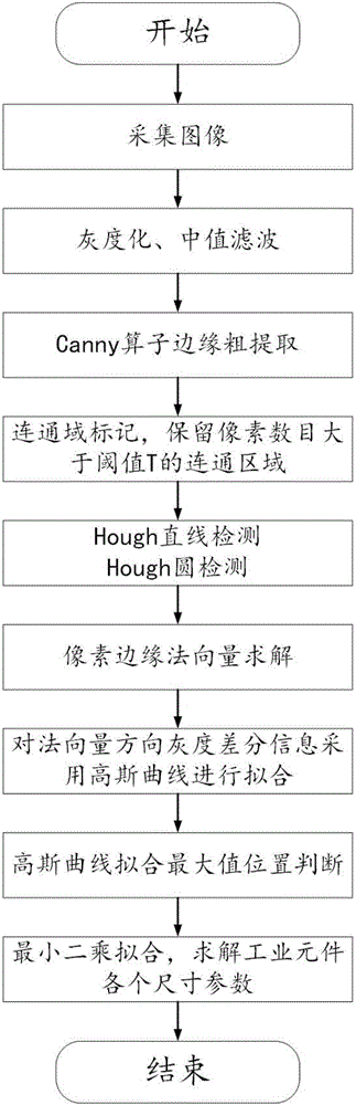
[0044]A sub-pixel measurement method of product size under the condition of industrial small-scale motion blur imaging, comprising the following steps:

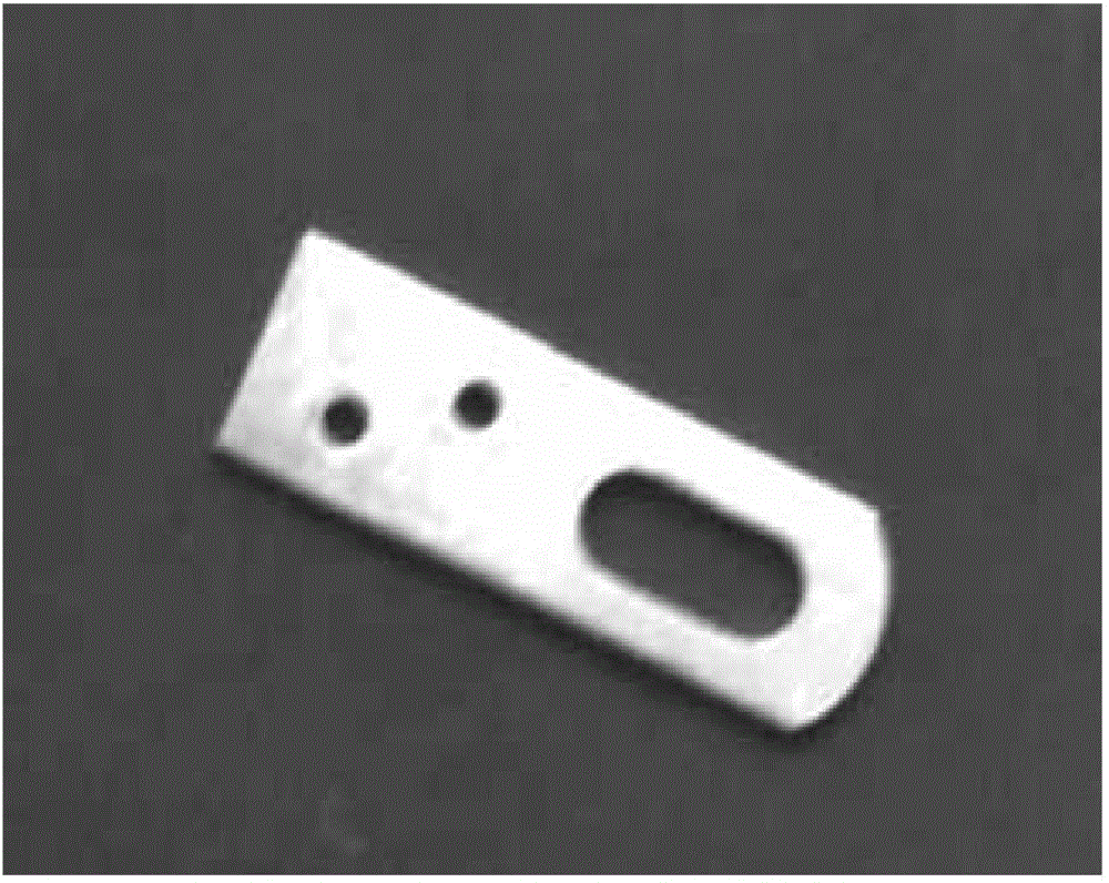
[0045] Step 1: Perform grayscale and median filter processing on the industrial component image collected by the industrial camera to obtain the original grayscale image;

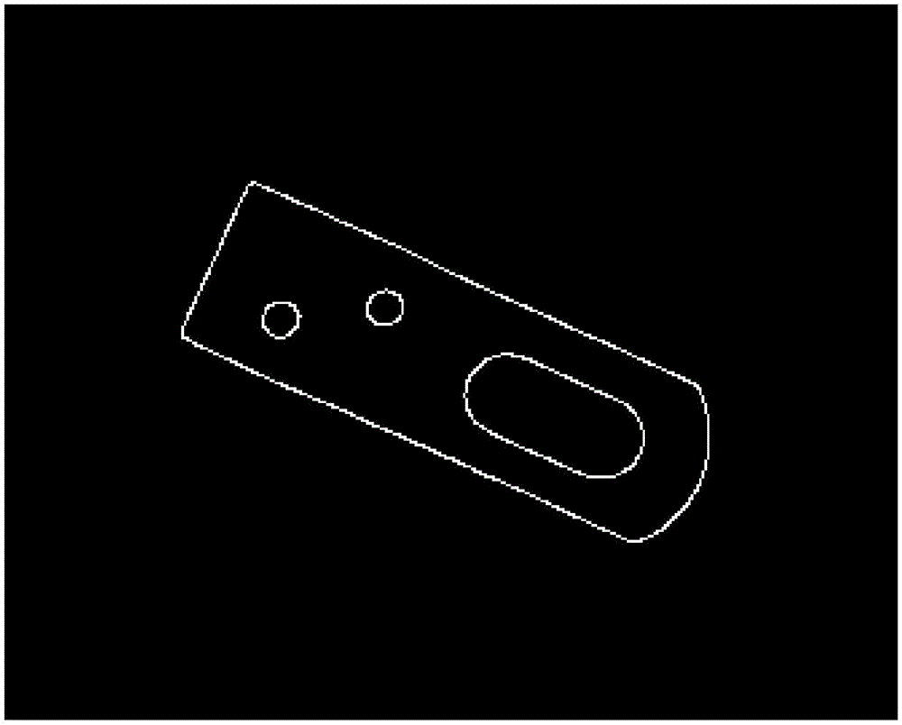
[0046] Step 2: For the original grayscale image, use the Canny operator to perform rough edge extraction to determine the edge position; perform local connected domain processing on the extracted edge pixels to obtain a complete edge binary image;

[0047] Step 3: Marking the connected domain on the complete edge binary image, screening the marked connected area, and retaining the connected area where the number of pixels contained in the connected area is greater than the preset threshold T;

[0048] Step 4: For the complete edge binary image obtained in step 3 after filter...

specific Embodiment approach 2

[0053] Specific implementation mode 2: Combining Figure 2a and Figure 2b Describe this embodiment,

[0054] The specific steps of performing local connected domain processing on the extracted edge pixels to obtain a complete edge binary image described in step 2 of this embodiment are as follows:

[0055] Step 21: Traverse each pixel on the edge position obtained by the rough extraction of the Canny edge;

[0056] Step 22. For each pixel, take the pixel as the center, and select a neighborhood window with a size of 3x3;

[0057] Step 2 and 3: If the number of connected domains in the neighborhood window is greater than or equal to 2, fill pixels between these connected domains to form a complete connected domain; otherwise, do not perform any operation; finally get Complete edge binary image;

[0058] Among them, the connected domain refers to the set of pixels that satisfies the 8-connectivity between the pixel positions.

[0059] Other steps and parameters are the sam...

specific Embodiment approach 3

[0061] The specific steps of screening the marked connected regions described in step 3 of this embodiment and retaining the connected regions with the number of pixels contained in the connected regions greater than the preset threshold T are as follows:

[0062] Step 31: Mark the connected domain of the complete edge binary image, at this time each complete edge is regarded as a connected domain and assigned a unique number;

[0063] Step 32: Analyze each connected domain: determine whether the number of pixels contained in the connected domain is greater than a preset threshold T;

[0064] Step 33: If it is greater than the preset threshold T, keep the connected domain; otherwise, remove the connected domain.

[0065] Other steps and parameters are the same as in the first or second embodiment.


PUM


Abstract

The invention provides a product dimension sub-pixel measurement method under an industrial microscale motion blurred imaging condition and relates to an industrial product dimension high precision measurement method based on machine visual sense. In order to solve the problem that the conventional mainstream sub-pixel measurement algorithm is low in precision when the industrial collection image has microscale motion blur, the method provided by the invention firstly carries out graying and median filtering processing to an industrial element image, and adopts a Canny operator to perform edge crude extraction and local connected domain processing; then the linear edge and the arc edge in the image are subjected to detection and recognition, the normal vector of the pixel contained in each edge in an original gray image is calculated, and the gray value difference of the edge pixel in the normal vector direction is calculated, and the position of the quadratic fit curve maximum is solved and determined; and finally, the position of the effective sub-pixel of the linear edge is subjected to linear least square fitting, and the each dimensional parameter of the industrial element is solved. The method is suitable for the sub-pixel measurement of the product dimension.

Description

technical field [0001] The invention relates to a high-precision measurement method of industrial product size based on machine vision. Background technique [0002] Dimensional measurement of industrial products is an important part of industrial inspection, and the level of measurement technology is an important indicator to measure the level of industrial development. Under the modern production mode of mass production, diversification of types, and strict quality control requirements, traditional manual measurement methods have been unable to meet the requirements of producers in terms of efficiency, cost, and informatization. Vision measurement technology based on image processing technology has shown significant advantages in flexibility, portability, cost, detection speed and accuracy, etc., and has been used in aerospace, aviation, automotive electronics and other high-precision manufacturing fields. wider application. [0003] In the visual measurement system, the...

Claims


Application Information

Patent Timeline
IPC IPC(8): G06T7/00G06T7/13G06T7/136G01B11/00
CPCG01B11/00G06T7/0004G06T2207/20032G06T2207/30108
Inventor 高会军靳万鑫于金泳林伟阳杨宪强孙光辉李湛滕军
Owner HARBIN INST OF TECH
Why Eureka
Try Eureka