
Portable radar perimeter security and protection system

A portable radar and security system technology, applied in the field of portable radar perimeter security systems, can solve problems such as large outdoor surveillance, weather, light influence, and inability to achieve, achieve high radar resolution, strong penetrating ability, and reduce errors. The effect of reporting

Inactive Publication Date: 2017-05-10
秦皇岛博微智能科技有限公司
View PDF0 Cites 21 Cited by
  • Summary
  • Abstract
  • Description
  • Claims
  • Application Information

AI Technical Summary

Problems solved by technology

[0007] The main defects of the portable video surveillance system are: equipment installation is cumbersome, cable transmission is required, the intrusion point cannot be actively located, the detection range is small, and it is greatly affected by weather and light; the reliability of the alarm algorithm is low
[0011] 2. The protection range is small
Due to the straight-line propagation characteristics of infrared / laser, portable optical security systems can only establish a very limited detection area, which is easily crossed by intruders;
[0012] 3. No ranging capability
Restricted by factors such as lens, camera field of view, and camera pointing, video technology cannot provide real-time, full-area monitoring. Image recognition and automatic tracking and alarm technology has great limitations, and large outdoor monitoring cannot yet be realized.

Method used


Image

  • Portable radar perimeter security and protection system
  • Portable radar perimeter security and protection system

Examples


Embodiment Construction

[0039] Below in conjunction with accompanying drawing and specific embodiment the present invention is described in further detail:

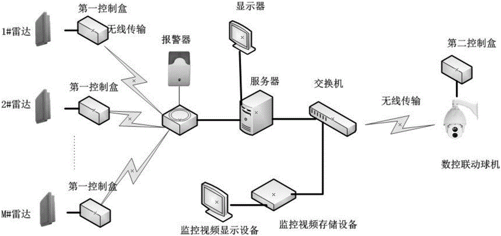
[0040] A portable radar perimeter security system of the present invention, its system topology is as follows figure 1 As shown, the system includes a radar, a first control box, a digital control dome machine, a second control box, a server, a display of the server, a switch, a monitoring video display device and an alarm device;

[0041] In specific implementation, the system can be applied to temporary perimeters of places with a high level of security protection, such as parking aprons and key temporary protection objects. The standard version of the system uses 4 radars and 1 CNC linkage dome machine for linkage. The warning range of each radar is one side, and one CNC linkage dome machine monitors the entire security area; the four radars form a closed loop.

[0042]The server, the numerical control linkage ball machine, the wireless devi...


PUM


Abstract

The invention provides a portable radar perimeter security and protection system. The portable radar perimeter security and protection system comprises radars, first control boxes, a numerical control linkage dome camera, a second control box, a server, a displayer of the server, a switch, a monitoring video display device and an alarm device. The server, the numerical control linkage dome camera, the wireless equipment, the radars, the monitoring video display device and the alarm device are connected by the wireless network. The server is equipped with the portable perimeter security and protection system software; the core of the software is the control of 3D linkage of the radars and the numerical control linkage dome camera; the algorithm adopted by the linkage control is presetting the space coordinates of the left, center and right 3 points of the radars and the numerical control linkage dome camera, and the input data is the target location detected by the radars, and the calculating result which is calculated according to trigonometric function is the PTZ 3D coordinate of the numerical control linkage dome camera. The first control boxes are used for supplying power to the radars, and the second control box is used for supplying power to the numerical control linkage dome camera. The switch provides the connection ports for a plurality of cables, used for connecting the server, the monitoring video display device, and the numerical control linkage dome camera; and the switch adopts star topology and realizes the data exchange among the devices in the network.

Description

technical field [0001] The invention relates to a security system, in particular to a portable radar perimeter security system. Background technique [0002] The perimeter alarm system is an alarm system, which is an alarm trigger system composed of perimeter alarm detectors, alarm hosts, and transmission media. In recent years, as people pay more attention to their own personal and property safety, perimeter alarm, as an integral part of security alarm, has also been valued by the majority of security engineering companies and end users, and more and more people pay attention to perimeter alarms. The principle of the perimeter alarm is mostly: the front end of the detector senses the alarm information, if someone invades and triggers the alarm, the perimeter alarm detector will transmit the detected alarm signal to the alarm host, and the alarm host will send an alarm through the linkage device or sound The device prompts the front-end alarm. [0003] For industrial sites...

Claims


Application Information

Patent Timeline
Patent Type & Authority Applications(China)
IPC IPC(8): H04N7/18G08B13/24G01S13/88
CPCH04N7/18G01S13/886G08B13/24
Inventor 肖猛胡振鹏朱德良
Owner 秦皇岛博微智能科技有限公司
Learn More