Valve for hydraulic damper

A hydraulic shock absorber and pressure technology, applied in the field of hydraulic shock absorbers, can solve the problems of displacement of structural elements, no vibration reduction effect, and inability to realize relative displacement of structural elements.

Active Publication Date: 2017-05-10
LISEGA SE
View PDF9 Cites 11 Cited by
  • Summary
  • Abstract
  • Description
  • Claims
  • Application Information

AI Technical Summary

Problems solved by technology

[0006] However, the traditional hydraulic shock absorber has the disadvantage that when the force between the structural elements exceeds the lower limit, the valve will suddenly open, which may cause severe displacement of the structural elements
Furthermore, conventional hydraulic shock absorbers are only suitable for absorbing the forces between the structural elements to which they are attached if these forces remain within a certain limited range
This is because if the force on the hydraulic damper is too low and the piston then cannot or has difficulty moving in its working chamber, the valve in the piston will not open and there will be

Method used


Image

  • Valve for hydraulic damper
  • Valve for hydraulic damper
  • Valve for hydraulic damper

Examples


Embodiment Construction

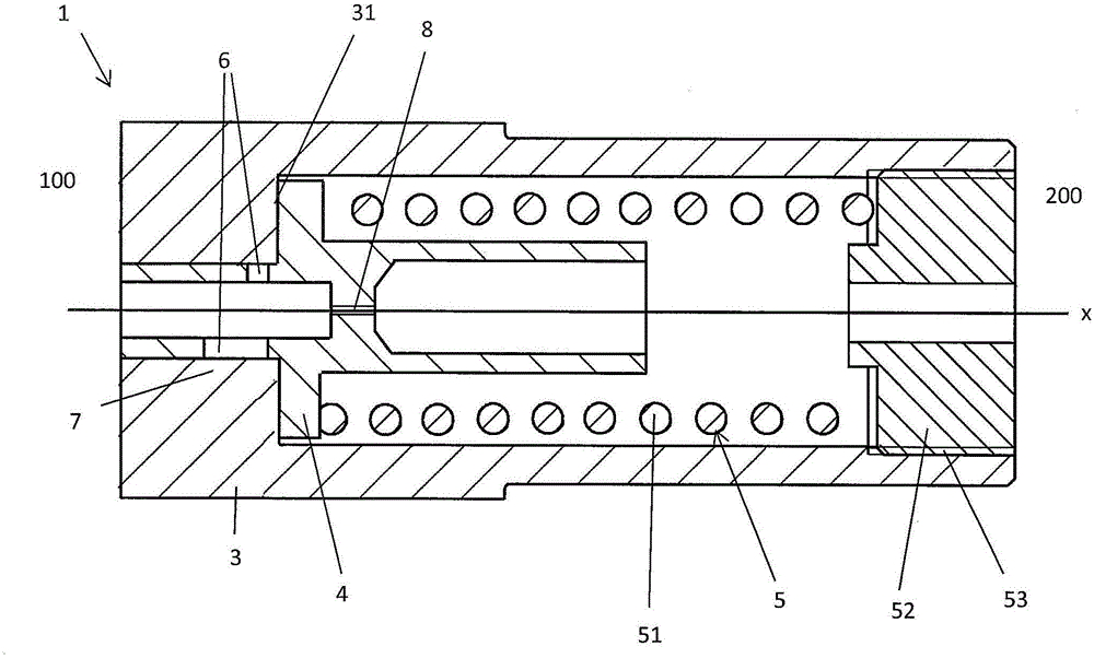
[0077] Figure 1a An exemplary embodiment of a valve 1 according to the invention is shown in a schematic sectional view. Figure 1a Valve 1 is shown in an inoperative position. The valve 1 comprises a seat element 3 and a moving element 4 . The seat element 3 has a cylinder section in the form of a hollow cylinder with a closed cylinder housing section 7 . This cylinder section of the seat element 3 holds a section of the displacement element 4 which is also configured as a hollow cylinder which has a channel 6 in its cylinder housing. The hollow cylinder section of the moving element 4 is loosely fitted into the above-mentioned hollow cylinder section of the seat element 3 . The moving element 4 and the seat element 3 guide each other on two sections, whereby the play between the moving element 4 and the seat element 3 is sufficient to allow a small amount of hydraulic fluid to penetrate between the moving element 4 and the seat element 3, thereby allowing the Lubrication ...


PUM


Abstract

The invention relates to a valve (1) to ensure pressure compensation between subchambers (21, 22) of a hydraulic damper (2), wherein the valve (1) comprises a first side (100) for connection to a first subchamber (21) and a second side (200) for connection to a second subchamber (22), the valve (1) is designed to shut off in its rest position a flow of fluid between the two sides (100, 200) and comprises, when deflected from its rest position, a passage channel with a passage cross-section for admitting the flow of fluid, the valve (1) comprises two valve elements (3, 4) guided towards each other and movable towards each other along a path of movement in a movement direction x, one of the two valve elements (3, 4) is designed as a moving element (4) and the other valve element as a seat element (3), a pressure can be applied to the moving element (4), on the load side thereof, by a fluid coming from the first side (100), generating an effective force for moving the moving element (4) in the moving direction x, and the moving element (4) is connected to a spring system (5) which applies to the moving element (4) a spring force, generating a restoring force opposite to the effective moving force. At least one of the valve elements (3, 4) comprises a cylinder section comprising a plurality of passages (6), the passage channel runs through at least some of the passages (6) and the passage cross-section is limited by a cross-section of these passages (6), while the other valve element (3, 4) comprises a closed cylindrical surface (7) which lies on the one valve element (3, 4) in the rest position, shutting off the flow of fluid, and the passage cross-section can be adjusted by the deflection of the valve (1) as a result of the movement of the moving element (4) towards the seat element (3) in the direction of movement x, the passage cross-section increasing with the deflection.

Description

technical field [0001] The invention relates to a valve according to the preamble of claim 1 for ensuring pressure equalization between two subchambers of a hydraulic shock absorber. The invention also relates to a hydraulic shock absorber. Background technique [0002] Common hydraulic shock absorbers are used to dampen impact forces, such as impacts on structural elements. Typical hydraulic shock absorbers are used, for example, to damp vibrations in structures such as bridges or high-rise buildings that may occur during earthquakes. Hydraulic shock absorbers are used for this purpose, for example, in cable shock absorbers. Typical hydraulic shock absorbers are designed to mitigate the risk that sudden impacts may separate supporting structural elements. Common hydraulic shock absorbers are thus designed to dampen such shocks. Due to the considerable forces that occur in the area of ​​application of such hydraulic shock absorbers, these have to be constructed particula...

Claims


Application Information

Patent Timeline
IPC IPC(8): F16F9/512
CPCF16F9/5126F16F9/064F16F9/16F16F9/512F16F9/06F16F9/325F16F9/34F16F9/369
Inventor J·贝尔纳特H-W·朗热G·施密特
Owner LISEGA SE
Why Eureka
Try Eureka