
Extraction apparatus

An extraction device and extraction agent technology, applied in solvent extraction, gaseous solvent extraction, liquid solution solvent extraction, etc., can solve problems such as inability to distribute, difficult to achieve uniformity, uncontrollable oil film thickness on the surface of the dispersed phase of bubbles in the oil film, etc. Achieve the effect of uniform size, easy separation and long contact time

Inactive Publication Date: 2017-05-17
INST OF PROCESS ENG CHINESE ACAD OF SCI
View PDF6 Cites 7 Cited by
  • Summary
  • Abstract
  • Description
  • Claims
  • Application Information

AI Technical Summary

Problems solved by technology

However, the realization of this method depends on the condensation rate of kerosene hot steam in the aqueous solution, and the thickness of the oil film on the surface of the generated bubble-in-oil dispersed phase cannot be controlled, and a stable bubble-in-oil dispersed phase cannot be obtained.
Although the existing technology also proposes a technical solution using a nested structure of inner and outer tubes, the inner tube blows gas and the outer tube supplies the oil phase, and disperses the small-volume oil phase with air bubbles, which can directly produce an oil film coated with an oil film in the aqueous solution Bubble-containing dispersed phase, the dispersion state of the small-volume oil phase in the large-volume water phase is easy to control artificially. However, the oil bubble distribution generator proposed in it cannot or is difficult to achieve uniform distribution of the oil chamber and the air chamber. In actual operation It is difficult to get evenly dispersed oil bubbles in

Method used


Image

  • Extraction apparatus
  • Extraction apparatus

Examples


Embodiment Construction

[0022] The technical solutions of the present invention will be further described below in conjunction with the accompanying drawings and through specific implementation methods.

[0023] Preferred embodiment:

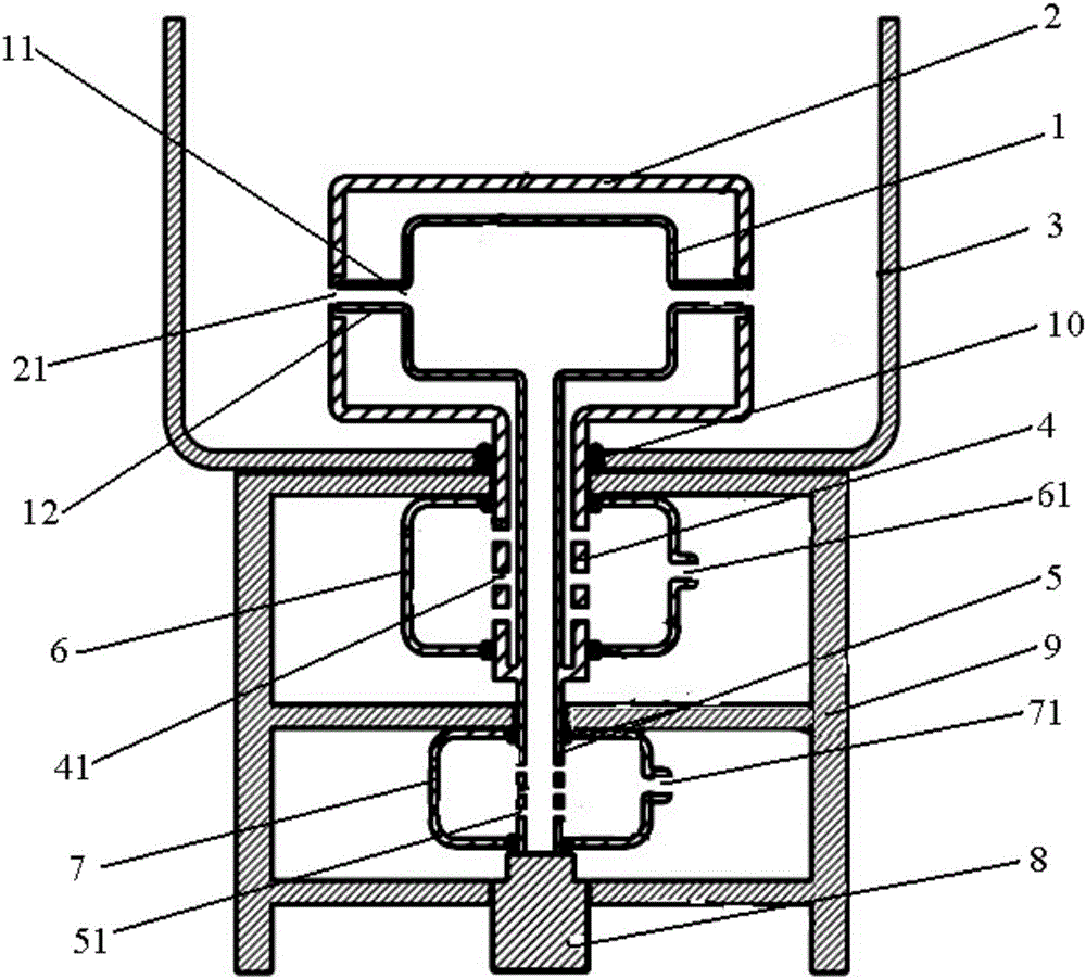
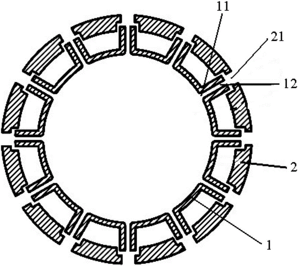
[0024] This preferred embodiment provides an extraction device, which is mainly used in a large phase extraction system. see figure 1 and figure 2 The extraction device provided in this preferred embodiment includes a gas chamber 1 and a first solvent chamber 2 sleeved outside the gas chamber 1, the gas chamber 1 and the first solvent chamber 2 are placed in the second solvent chamber 3, and the first solvent chamber 2 is used to contain the light phase extractant, the second solvent chamber 3 is used to contain the heavy phase to-be-extracted liquid, the first solvent chamber 2 communicates with the extractant source located outside the second solvent chamber 3, and the gas chamber 1 is connected to the second solvent chamber The gas source outside the chamber 3 i...


PUM


Abstract

The invention discloses an extraction apparatus, belongs to the technical field of extraction, and is designed for solving the problem of nonuniform distribution of extractant in the prior apparatus. The extraction apparatus comprises an air chamber and a first solvent chamber which is sleeved outside the air chamber, the air chamber and the first solvent chamber are placed in a second solvent chamber, the first solvent chamber is used for containing a light phase extractant, the second solvent chamber is used for containing a heavy phase liquid to be extracted, the first solvent chamber and a extractant source which is positioned outside the solvent chamber are communicated, and the air chamber and a gas source which is positioned outside the second solvent chamber are communicated; a side wall of the air chamber is circumferentially and uniformly provided with several gas outlets, a side wall of the first solvent chamber corresponding to the position of the gas outlets is uniformly provided with several first outlets, and each gas outlet is communicated to the inner side of the corresponding first outlet or into the first outlet. In the extraction apparatus, oil gas bubble generation points are uniformly distributed, so that the extractant can be uniformly distributed in the liquid to be extracted with good extraction effects.

Description

technical field [0001] The invention relates to the technical field of chemical separation devices, in particular to an extraction device. Background technique [0002] Solvent extraction is an important chemical separation technology, which has the advantages of high separation efficiency and easy operation, and is widely used in petrochemical, pharmaceutical, hydrometallurgy, environmental treatment and other fields. The solvent extraction process involves the reaction and mass transfer process between the two immiscible liquid phases. To achieve uniform mixing of the two immiscible liquid phases, one of the phases must be uniformly dispersed into the other phase. This provides a larger two-phase contact area. Traditional extraction equipment is divided into three categories: mixing-clarifying extraction tank, tower extractor, and centrifugal extractor. These equipment can realize the two phases of water and oil that are immiscible in the extraction process are mixed firs...

Claims


Application Information

Patent Timeline
Patent Type & Authority Applications(China)
IPC IPC(8): B01D11/04
CPCB01D11/04B01D2011/007
Inventor 潘峰赵君梅安震涛刘会洲
Owner INST OF PROCESS ENG CHINESE ACAD OF SCI
Learn More