
Bionic road roller steel wheel and operation method thereof

A technology of road roller and bionic pressure, which is applied in the direction of roads, roads, road repair, etc., can solve problems such as loose bonding, and achieve the effects of low cost, convenient disassembly and assembly, and improved practical scope.

Inactive Publication Date: 2017-05-17
CHANGAN UNIV
View PDF4 Cites 6 Cited by
  • Summary
  • Abstract
  • Description
  • Claims
  • Application Information

AI Technical Summary

Problems solved by technology

[0005] The purpose of the present invention is to provide a bionic road roller steel wheel and its operation method, in order to solve the common problem of loose bonding between rigid and flexible layers of cement-stabilized soil

Method used


Image

  • Bionic road roller steel wheel and operation method thereof
  • Bionic road roller steel wheel and operation method thereof
  • Bionic road roller steel wheel and operation method thereof

Examples


Embodiment Construction

[0028] Below in conjunction with accompanying drawing, the present invention is further described:

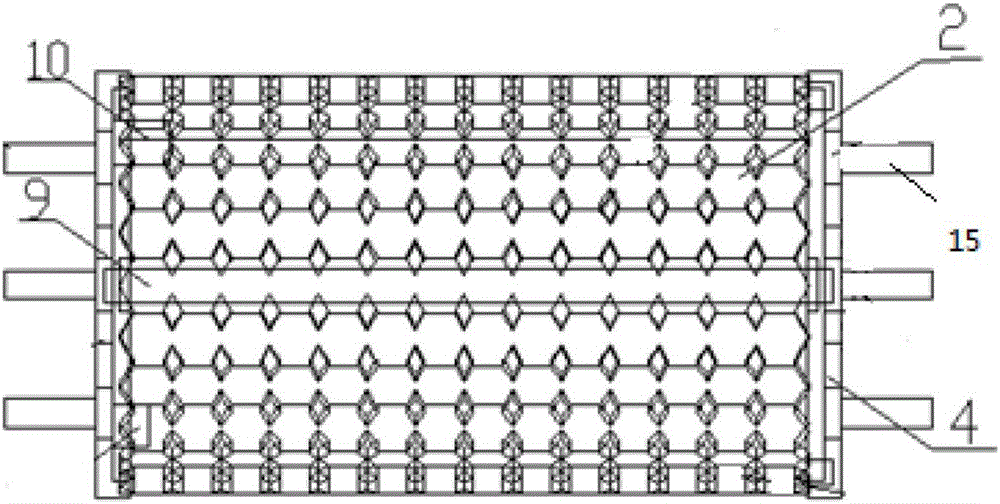
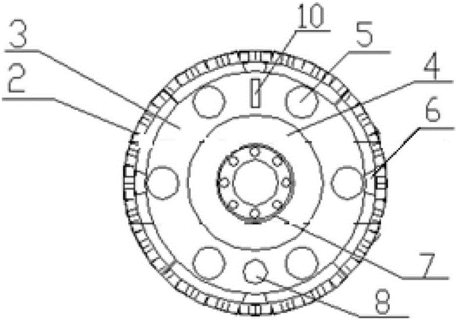
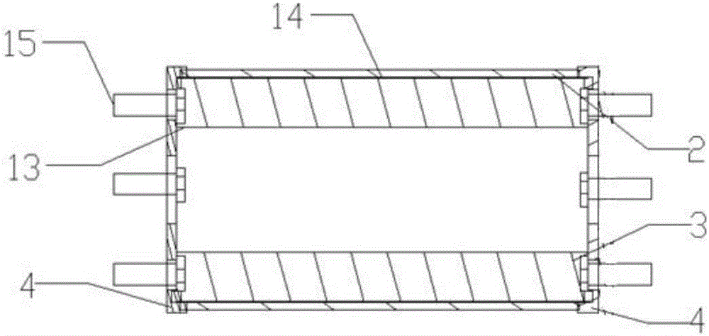
[0029] see Figure 1 to Figure 7 , a steel wheel of a bionic road roller, comprising a steel wheel 3, a bionic compaction device 2, a fixed end cover 4, an electromagnetic positioning column 9 and a polygonal draft prism 12; the steel wheel 3 is cylindrical, and the side of the steel wheel 3 is parallel to The steel wheel 3 axis is provided with some electromagnetic positioning columns 9; the fixed end cover 4 is circular, and the two ends of the steel wheel 3 are all concentrically fixed with the fixed end cover 4, and the area of ​​the fixed end cover 4 is greater than that of the steel wheel 3 ends. area; the two ends of the electromagnetic positioning column 9 are fixed on the fixed end cover 4; the bionic compacting device 2 is arc-shaped, and the number of the bionic compacting device 2 is the same as the number of the electromagnetic positioning column 9, and each bionic...


PUM


Abstract

The invention discloses a bionic road roller steel wheel and an operation method thereof. The bionic road roller steel wheel comprises a steel wheel, a bionic compaction device, a fixed end cover, an electromagnetic positioning column and a polygon drawing prism. According to the bionic road roller steel wheel and the operation method thereof, the bionic compaction device carries out rough surface rolling on a rigid-flexible combined surface of cement-stabilized soil by using a bionic technology; and the steel wheel carries out plane compaction on a pavement. The bionic road roller steel wheel can be applicable to rolling of a plane and a rough surface at the same time, a user is greatly facilitated, the practical range is improved, and the bionic road roller steel wheel has the advantages of being simple in structure, convenient to disassemble and assemble, reasonable in setting and low in cost.

Description

technical field [0001] The invention belongs to the technical field of road traffic machinery, and in particular relates to a steel wheel of a bionic road roller and an operating method thereof. Background technique [0002] Road rollers belong to the category of road equipment in construction machinery. They are widely used in the filling and compaction operations of large-scale engineering projects such as high-grade highways, railways, airport runways, dams, and stadiums. They can roll sandy, semi-cohesive and cohesive soils, Roadbed stabilized soil and asphalt concrete pavement layer. [0003] With the gravity of the machine itself, it is suitable for various compaction operations, so that the rolled layer will be permanently deformed and compacted. It is divided into two types: steel wheel type and tire type. The grinding wheel structure includes smooth grinding, groove grinding and sheep foot grinding. Smooth milling is the most common application and is mainly used...

Claims


Application Information

Patent Timeline
Patent Type & Authority Applications(China)
IPC IPC(8): E01C19/28
CPCE01C19/28E01C19/286
Inventor 陈世斌姚运仕余娜杨双建刘鑫马景存赵轩
Owner CHANGAN UNIV
Learn More