
Quick cleaning device for boulders in cast-in-place pile and construction process thereof

A technology of cleaning device and cast-in-situ pile, which is applied in the direction of sheet pile wall, foundation structure engineering, construction, etc., can solve the problems of increasing labor cost and equipment rental fee, not considering the load of punching piling machine, and not meeting the project schedule requirements, etc. Achieve the effects of improving hole forming efficiency, improving efficiency and shortening construction period

Inactive Publication Date: 2017-05-17
CCCC THIRD HARBOR ENG +1
View PDF10 Cites 11 Cited by
  • Summary
  • Abstract
  • Description
  • Claims
  • Application Information

AI Technical Summary

Problems solved by technology

[0004] However, since most of the cast-in-place piles in the project are cast-in-place piles above water, the load of the perforated pile driver was not considered at the beginning of the design of the cast-in-place pile platform on the water, so if punching piling equipment is used, the existing cast-in-situ pile platform needs to be reinforced, which will cost a lot of money Labor and material costs and the construction period need to be extended. The drilling time for cast-in-place piles is about 20 hours without the influence of boulders, and about 70 hours for perforated pile drivers if boulders are encountered. It takes 50 hours more processing time to make a single pile with a punching pile driver to crush stones, which does not meet the project schedule requirements, and also greatly increases labor costs and equipment rental costs

Method used


Image

  • Quick cleaning device for boulders in cast-in-place pile and construction process thereof
  • Quick cleaning device for boulders in cast-in-place pile and construction process thereof
  • Quick cleaning device for boulders in cast-in-place pile and construction process thereof

Examples


Embodiment Construction

[0029] The present invention will be further explained below in conjunction with the accompanying drawings and specific embodiments. It should be understood that the following specific embodiments are only used to illustrate the present invention and are not intended to limit the scope of the present invention. It should be noted that the words "front", "rear", "left", "right", "upper" and "lower" used in the following description refer to the directions in the drawings, and the words "inner" and "outer ” refer to directions towards or away from the geometric center of a particular part, respectively.

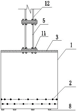
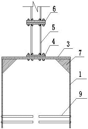
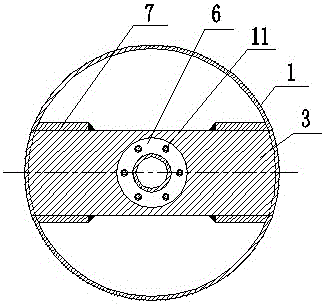
[0030] As shown in the figure, the device for quickly cleaning boulders in cast-in-situ piles according to the present invention includes a drill tube 1 and a wire comb 2. The drill tube 1 is a cylindrical structure with two ends open, and a top plate 3 is arranged above the drill tube 1. , the top plate is connected to flange two 4 in the middle, and the middle of the flange t...


PUM


Abstract

The invention discloses a quick cleaning device for boulders in a cast-in-place pile. The quick cleaning device comprises a drilling cylinder and steel wire comb teeth, a top plate is arranged on the upper portion of the drilling cylinder, a second flange is connected in the middle of the top plate, the middle of the second flange is connected with stress rods, grouting holes are formed in the middle of the stress rods, the upper portions of the stress rods are connected with drilling rods through a first flange, and the lower portions of the stress rods extend downwards to the interior of the drilling cylinder. Rib plates are arranged between the side face of the top plate and the inner wall of the drilling cylinder, and 4-10 alloy drilling heads are arranged at the bottom of the drilling cylinder. The steel wire comb teeth are arranged on the lower portion inside the drilling cylinder, the steel wire comb teeth are divided into an upper layer and a lower layer, each layer of steel wire comb teeth is composed of 10-30 steel wire ropes, and stone filling holes are formed between the steel wire comb teeth. According to the quick cleaning device, quick boulder cleaning is achieved, significant effects are achieved particularly on the boulders with small volumes and numbers, manufacturing cost is low, and operation is easy. The drilling cylinder needs to be replaced instead of a drilling machine when used, so that compared with a punching piling machine, pore forming efficiency is greatly improved, the construction period is shortened, efficiency is improved, and practicability is strong.

Description

technical field [0001] The invention belongs to the technical field of cast-in-place pile foundations in construction engineering, and in particular relates to a quick-cleaning device for bored stones in cast-in-place piles and a construction process thereof. Background technique [0002] During the construction process of the riverside wharf, several bent foundations need to be arranged at the root of the approach bridge. The approach bridge is perpendicular to the levee and connected sequentially. The area where the cast-in-place piles of the approach bridge are located is within the scope of the riprap bottom protection of the Yangtze River embankment, and the thickness of the riprap layer is about 5m. Left and right, the cast-in-situ piles range in length from 40-54m, and the existing riprap layer of the embankment needs to be penetrated during the hole-forming construction. The riprap construction was carried out, and the depth of the riprap was greater than 5m. After t...

Claims


Application Information

Patent Timeline
Patent Type & Authority Applications(China)
IPC IPC(8): E02D13/08
CPCE02D13/08
Inventor 顾晓彬戴志培钟宇明孙发荣张福春
Owner CCCC THIRD HARBOR ENG
Learn More