
Side wing foundation scour-resistant reinforcing structure for enhancing stability of road shoulder wall

A technology for strengthening structures and foundations. It is used in infrastructure engineering, underwater structures, water conservancy projects and other directions. It can solve problems such as high engineering costs, increased section size and foundation depth, and poor integrity, and achieves investment savings and savings. Engineering cost and maintenance cost, good effect

Inactive Publication Date: 2017-05-17
新疆维吾尔自治区交通规划勘察设计研究院
View PDF6 Cites 1 Cited by
  • Summary
  • Abstract
  • Description
  • Claims
  • Application Information

AI Technical Summary

Problems solved by technology

In the past, the shoulder wall often used the conventional form of leaning straight back. In the structural design, factors such as cost control, local materials and construction convenience were considered, and the mortar masonry structure or riprap concrete was poured in layers to show its overall integrity. Poor performance; or for safety reasons, reinforced concrete structure is adopted, section size and foundation depth are increased, resulting in high engineering cost

Method used


Image

  • Side wing foundation scour-resistant reinforcing structure for enhancing stability of road shoulder wall
  • Side wing foundation scour-resistant reinforcing structure for enhancing stability of road shoulder wall
  • Side wing foundation scour-resistant reinforcing structure for enhancing stability of road shoulder wall

Examples


Embodiment 1

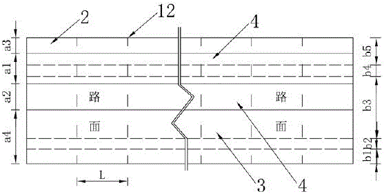
[0036] Embodiment one: if figure 1 , 2 , 3, and 4 show that the slope of the river is 140‰, and the subgrade height is 6m. On the river bed, build a 100m-long road shoulder wall 1, adopt the shoulder wall 1 with the L-shaped beam tooth wall foundation 2 at the wall toe and the L-shaped beam tooth wall foundation 3 at the wall heel, and adopt a convex line wall The interior surface 5 optimizes the structure of the inner wing of the shoulder wall 1 . First construct the L-shaped beam tooth wall foundation 2 at the wall toe and the L-shaped beam tooth wall foundation 3 at the wall heel, and then construct the upper wall 4 on the road. The inner and outer wings of the shoulder wall are respectively provided with a wall toe L-shaped beam tooth wall foundation 2 and a wall heel L-shaped beam tooth wall foundation 3 for reinforcement, and are connected with the upper wall body 4 as a whole.

[0037] A flank foundation anti-scour reinforcement structure for enhancing the stability ...

Embodiment 2

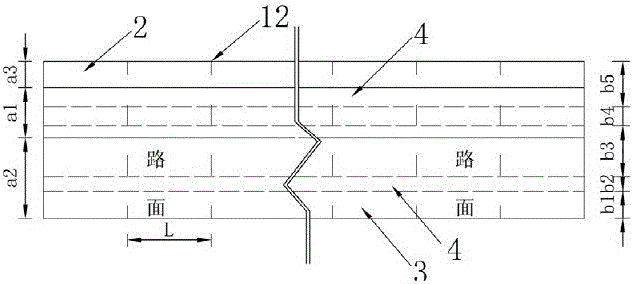
[0053] Embodiment two: if figure 1 , 5 As shown in , 6, the slope of the river is 52‰, and the subgrade height is 2.5m. A flank foundation anti-scour reinforcement structure for enhancing the stability of the shoulder wall includes a base embedded in the river bed, and an upper wall 4 established on the base, the base includes the upper wall 4, The wall toe L-shaped beam tooth wall foundation 2 on the outer two sides and the wall heel L-shaped beam tooth wall foundation 3, the wall outer side 6 of the upper wall 4 is an inclined plane, and the wall inner side 5 is a broken line surface .

[0054] The same as Embodiment 1 will not be repeated, the difference is: the L-shaped beam tooth wall foundation 3 at the wall heel is arranged on the inner side of the lower end surface of the upper wall 4, the wall heel pressure plate 8 and the wall heel tooth wall 9 The outer side is on the same vertical plane and is continuously connected with the inner side 5 of the wall, and the inn...

Embodiment 3

[0059] Embodiment three: as figure 1 , 2 , 3, 4, 7, and 8, a flank foundation anti-scour reinforcement structure for enhancing the stability of the shoulder wall includes a base embedded in the river bed, and an upper wall 4 set up on the base. The base includes a wall toe L-shaped beam tooth wall foundation 2 and a wall heel L-shaped beam tooth wall foundation 3 which are arranged on the inner and outer sides of the upper wall body 4. The wall outer surface 6 of the upper wall body 4 is One inclined plane, the inner side surface 5 of the wall is a broken line plane.

[0060] The same as the first embodiment will not be repeated, the difference is: when the shoulder wall 1 is eroded by the water flow at the head and tail ends of the longitudinal extension, the two single shoulder walls 1 at the head and tail ends are poured in a fully enclosed way To prevent water from entering the gap between the L-shaped beam tooth wall foundation 2 at the toe of the wall and the L-shaped ...


PUM


Abstract

The invention relates to a side wing foundation scour-resistant reinforcing structure for enhancing stability of a road shoulder wall. The side wing foundation scour-resistant reinforcing structure comprises a base and an upper wall body, wherein the base is arranged in a river bed material in an embedded manner, and the upper wall body is arranged on the base. The base comprises wall toe L-shaped beam type key wall foundations and a wall heel L-shaped beam type key wall foundation, wherein the wall toe L-shaped beam type key wall foundations are arranged at the inner side and the outer side of the upper wall body correspondingly. The outer side face of a wall body of the upper wall body is an oblique face, and the inner side face of the wall body is a broken line face. According to the side wing foundation scour-resistant reinforcing structure for enhancing stability of the road shoulder wall, the advantages, such as scour resistance, differential settlement resistance, skid resistance and overturning resistance, of the L-shape beam type key wall foundations are fully utilized; fluid-scour resistance, integrity of differential settlement resistance and stability of skid resistance and overturning resistance of a side wall are improved in a segmented manner; scour resistance of an outer side wing and reinforcing of the inner side edge of the road shoulder wall can be combined organically; the situation that safety of the whole road shoulder wall is endangered due to local damage of the side wall is avoided; it is fully guaranteed that the road shoulder wall plays a normal role in support, blocking and protection; and engineering cost and maintenance cost are saved.

Description

technical field [0001] The invention relates to a road shoulder protection technology, in particular to a flank foundation anti-shock reinforcement structure for enhancing the stability of a road shoulder wall. Background technique [0002] Water damage is one of the main disease types of mountainous roads. It is widely distributed and seriously harmful. In addition to directly destroying roadbeds and bridges and culverts, water damage can also induce secondary disasters such as suspended roadbeds, deformation of retaining walls, and cracks in road surfaces, resulting in Road breaks and traffic jams seriously affect and endanger the operation of transportation, and even directly threaten the safety of life and property. [0003] In recent years, with the deepening of my country's western development and the national "Belt and Road" strategy, road construction will usher in a new round of great development, and the demand for engineering treatment of road water damage will be...

Claims


Application Information

Patent Timeline
Patent Type & Authority Applications(China)
IPC IPC(8): E02D17/20E02D29/02
CPCE02D17/20E02D29/0283
Inventor 魏学利李宾杨新龙宋学艺陈发明赵怀义李伟陈宝成
Owner 新疆维吾尔自治区交通规划勘察设计研究院
Learn More