Rotating wheel linkage adjustment structure of furniture sliding door

A technology for adjusting structures and turning wheels, which is applied in door/window fittings, building structures, and wing leaf suspension devices, etc. It can solve the problems of not having position adjustment, not being able to use sliding doors, and not being able to meet the use requirements, etc., to achieve improved Adjust the experiential effect

Active Publication Date: 2017-05-17
伍志勇
View PDF7 Cites 0 Cited by
  • Summary
  • Abstract
  • Description
  • Claims
  • Application Information

AI Technical Summary

Problems solved by technology

However, the structure is relatively complicated and costly, and the gap between the sliding seat, the sliding arm and the pendulum block is relatively large, which affects its aesthetics and is not convenient for processing and production. There will always be noise when the groove is closed and sliding, which does not meet the needs of users, and this structure can only be used for drawer slide rails, not for sliding doors, and does not have the function of position adjustment, which cannot meet the needs of users

Method used


Image

  • Rotating wheel linkage adjustment structure of furniture sliding door
  • Rotating wheel linkage adjustment structure of furniture sliding door
  • Rotating wheel linkage adjustment structure of furniture sliding door

Examples


Embodiment Construction

[0021] The present invention will be further described below in conjunction with the accompanying drawings and embodiments.

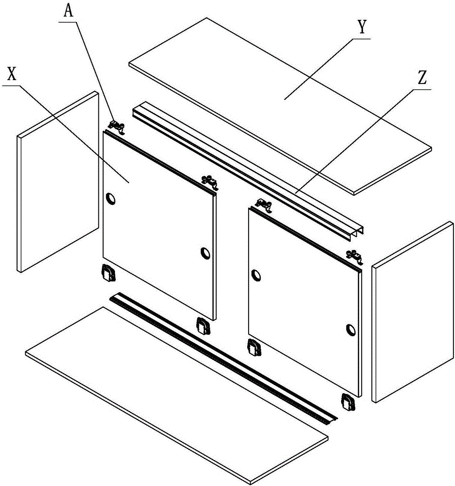
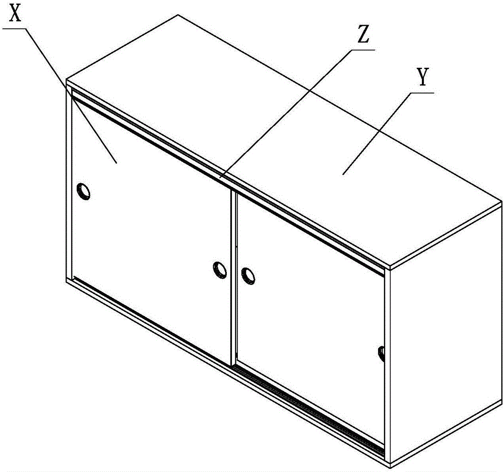
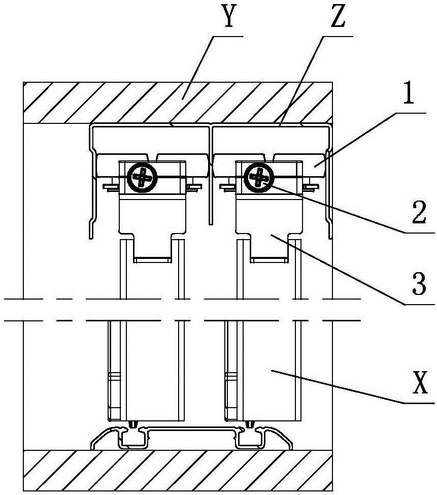
[0022] see figure 1 - Figure 8, the rotating wheel linkage adjustment structure of the sliding door of this furniture, including the rotating wheel adjusting device A, the rotating wheel adjusting device A includes a swinging element, a rotating wheel 1, an adjusting element 2 and a bracket element 3; wherein, the swinging element is provided with At least two of them are arranged on the support element 3 for swinging respectively. The rotating wheel 1 is provided with at least two corresponding to the swinging elements and positioned and rotated respectively on the swinging elements. At least two of the swinging elements are respectively provided with teeth, and pass through the The teeth are meshed with each other, and the adjustment element 2 is positioned and rotated on the bracket element 3, and the adjustment action part 2.1 is arranged on it; the...


PUM


Abstract

A rotating wheel linkage adjustment structure of a furniture sliding door comprises at least two swinging elements, at least two rotating wheels, an adjustment element and a support element. The swinging elements are arranged on the support element in a swinging mode. The rotating wheels correspond to the swinging elements and are positioned to the swinging elements correspondingly in a rotary mode. The at least two swinging elements are each provided with a tooth part, and are engaged and linked with one another through the tooth parts. The adjustment element is positioned on the support element in a rotary mode and provided with an adjustment acting part. The adjustment acting part is adjusted manually or through a tool. The adjustment element is positioned on the support element in a rotary mode, is engaged with the tooth part of one swinging element, and drives the swinging element to swing on the support element. The one swinging element drives the other swinging elements to swing simultaneously and/or synchronously relative to the support element in the reverse direction through the tooth part, so that the positions, relative to the support element, of the at least two rotating wheels are adjusted.

Description

technical field [0001] The invention relates to a rotating wheel linkage adjustment structure for a furniture sliding door. Background technique [0002] Chinese Patent Document No. CN101797102A disclosed a drawer slide rail on August 11, 2010. It includes a fixed slide rail and a moving slide rail. The slide seat is arranged on the fixed slide rail, and an inner slide groove, Sliding arm and pendulum block, one end of the sliding arm is connected with the pendulum block, the other end of the sliding arm is inserted into the inner chute to slide, the pendulum block is provided with an open slot, and the open slot is connected with the bumper set on the moving slide rail Correspondingly, the pendulum block is connected with one end of the tension spring, and the other end of the tension spring is connected with the sliding seat. The pendulum block is provided with a cavity for accommodating the swing arm, and an open groove is formed between one side of one end of the swing a...

Claims


Application Information

Patent Timeline
Patent Type & Authority Applications(China)
IPC IPC(8): E05D13/00
CPCE05D13/00
Inventor 伍志勇
Owner 伍志勇
Why Eureka
Try Eureka