Movement conversion device based on vehicle vibration

A technology of motion conversion and motion conversion mechanism, applied in the direction of the mechanism, engine, elastic engine, etc. that generate mechanical power, it can solve the problems of hydraulic pipeline leakage, low applicability, complex structure, etc., so as to prolong the service life and avoid energy The effect of loss, support to restore balance

Active Publication Date: 2017-05-17
SOUTHWEST JIAOTONG UNIV
View PDF22 Cites 10 Cited by
  • Summary
  • Abstract
  • Description
  • Claims
  • Application Information

AI Technical Summary

Problems solved by technology

[0003]According to the search, there are currently existing automobile vibration power generation devices, such as the Chinese patent No. 201420361017.5 titled "a new type of automobile vibration energy power generation device". Composed of a hydraulic system and a power generation system, the installation of too many system components is complicated, and there is a risk of leakage of the hydraulic pipeline during use
[0004] Another example is the Chinese patent No. 201210182790.0 titled "A Realization Method of Forced Vibration for Kinetic Energy Generation of Electric Vehicles", which uses gears and racks The meshing drives the elastic vibrating body to resonate at the frequency of the first break or effectively vibrate to generate kinetic energy. The structure is complex, there are requirements for the frequency of vibration, and the applicability is not high.

Method used


Image

  • Movement conversion device based on vehicle vibration
  • Movement conversion device based on vehicle vibration
  • Movement conversion device based on vehicle vibration

Examples


Embodiment Construction

[0020] The present invention will be further described in detail below in conjunction with the accompanying drawings and specific embodiments.

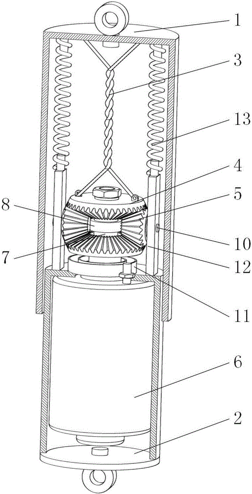
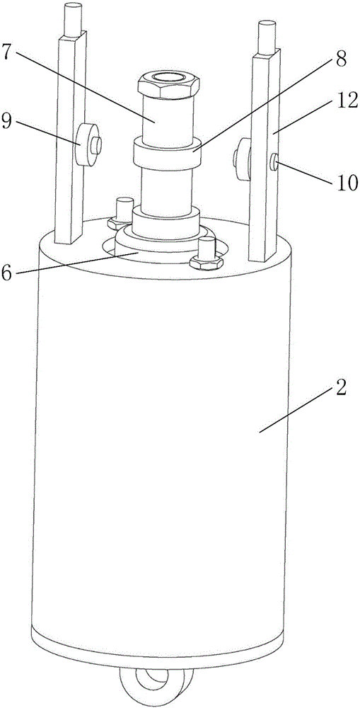
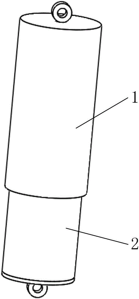
[0021] A motion conversion device based on vehicle vibration, including an upper sleeve 1, a lower sleeve 2, a motion conversion mechanism and a motor 6, the upper sleeve 1 and the lower sleeve 2 are clearance fit; the motor 6 is located on the lower sleeve 2 Inside, the motor shaft faces upward and is exposed at the opening of the lower sleeve 2; a thrust bearing 8 is provided in the middle of the motor shaft, and a one-way bearing 7 is provided above and below the thrust bearing 8; the one-way bearing 7 on the top and The lower one-way bearings 7 are respectively matched with a group of large bevel gears opposite to the tooth surface; one end of the steel wire rope 3 is located on the top inner side of the upper sleeve 1, and the other end is fixed to the axial back of the upper large bevel gear 1-4; the lower sleeve The two sides o...


PUM


Abstract

The invention provides a movement conversion device based on vehicle vibration and belongs to the technical field of mechanical movement conversion. The movement conversion device based on vehicle vibration can be effectively used for converting vertical movement into circular movement. A motor is located in a lower sleeve, and a motor shaft of the motor faces upwards and is exposed out of an opening of the lower sleeve. A thrust bearing is arranged in the middle of the motor shaft, and the upper side and the lower side of the thrust bearing are each provided with a one-way bearing. The upper one-way bearing and the lower one-way bearing are matched with a set of large bevel gears provided with opposite tooth surfaces separately. One end of a steel wire rope is located on the inner side of the top of an upper sleeve, and the other end of the steel wire rope is fixed to the axial back surface of the first large bevel gear located on the upper side. Vertical supports are arranged on two sides of an opening of the lower sleeve, spring limiting seats are arranged at the top ends of the supports, transverse shafts are arranged on the inner sides of the middles of the supports, two small bevel gears are matched with bearings arranged on the transverse shafts, one end of a volute spiral spring is fixed at the bottom of the second large bevel gear located on the lower side, and the other end of the volute spiral spring is fixed on the lower sleeve. The movement conversion device based on vehicle vibration is mainly used for devices for converting mechanical energy of vehicle vibration damping parts into electric energy.

Description

technical field [0001] The invention belongs to the technical field of mechanical motion conversion. Background technique [0002] With the excessive consumption of energy, alternative energy sources such as solar energy, wind energy, vibration energy, etc. are getting more and more attention. However, the collection of solar and wind energy is limited by many natural conditions. Harvesting of vibrational energy stands out due to its advantages such as practicality and power density. At present, vibration energy harvesting and power generation mainly include piezoelectric, electromagnetic and electrostatic. Compared with the other two methods, the electromagnetic method has the characteristics of low cost and high performance, and is ideal among vibration energy harvesting methods. The electromagnetic vibration energy harvesting device can be divided into direct cutting magnetic induction lines and rotating cutting magnetic induction lines converted into motors. Differen...

Claims


Application Information

Patent Timeline
IPC IPC(8): F03G7/08F03G1/02
CPCF03G1/02F03G7/08
Inventor 张祖涛潘宏烨漆令飞朱鑫
Owner SOUTHWEST JIAOTONG UNIV
Why Eureka
Try Eureka