
Robot joint reducer

A technology of robot joints and reducers, which is applied in the field of robots, can solve the problems of flexible output transmission error and precision to be further improved, high precision requirements for rigid gear processing, and high difficulty in rigid gear processing, so as to achieve strong load bearing capacity and repeated positioning The effect of high precision and large number of teeth

Active Publication Date: 2019-11-19
柔昊精密科技(苏州)有限公司
View PDF7 Cites 0 Cited by
  • Summary
  • Abstract
  • Description
  • Claims
  • Application Information

AI Technical Summary

Problems solved by technology

[0002] There are two types of existing robot joint reducers, one is rigid input and rigid output, such as RV reducer, which uses rigid input and rigid output, and the power on the input shaft is transmitted to the output shaft through rigid gears. The disadvantages are : 1. The rigid gear will be worn during the transmission process, which will cause a large transmission error when the rigid gear meshes with the output shaft, which is not conducive to output precision control
2. Because it uses rigid gears to mesh with the output shaft, it requires high machining accuracy for rigid gears, which makes the processing of rigid gears more difficult.
[0003] The other type is rigid input and flexible output, such as harmonic reducer, which uses rigid input and flexible output. The disadvantage is that the transmission error and accuracy of flexible output need to be further improved

Method used


Image

  • Robot joint reducer
  • Robot joint reducer
  • Robot joint reducer

Examples


Embodiment

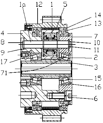
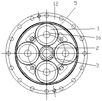
[0024] Example: see Figures 1 to 3 As shown, the robot joint reducer includes a planetary gear 1 and a sun gear 2 fixed on the power input shaft 3, the left box 4 and the right box 7 are fixed together by screws 6, and the left box 4 and the right box 7 are the same Axis line, the power input shaft 3 is coaxial with the left box body 4 and the right box body 7;

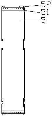
[0025] Internal teeth 51 are formed on the inner wall of the thin-walled elastic ring gear 5, and external teeth 52 are formed on the outer wall of the thin-walled elastic ring gear 5. The sun gear 2 meshes with the planetary gear 1, and the planetary gear 1 and the thin-walled elastic ring gear 5 The internal teeth 51 are meshed, and there are four planetary gears 1;

[0026] The planetary gear 1 is molded or fixed on the planetary gear shaft 1a, and the planetary gear shaft 1a is inserted into the preset holes of the left box body 4 and the right box body 7. The left end of the planetary gear shaft 1a is screwed w...


PUM


Abstract

Provided is a robot joint speed reducer. A sun gear is fixed to a power input shaft. A left box and a right box are fixed together through screws and share the same axis. The power input shaft shares the same axis with the left box and the right box. Internal teeth are formed on the inner wall of a thin-wall elastic gear ring. External teeth are formed on the outer wall of the thin-wall elastic gear ring. The sun gear is engaged with planetary gears, the planetary gears are engaged with the internal teeth of the thin-wall elastic gear ring, and the number of the planetary gears is four. Cylindrical rollers are installed on second retainers. The second retainers and the cylindrical rollers are clamped among the power input shaft and the left box and the right box. Due to the fact that the interior and exterior of the thin-wall elastic gear ring are both provided with the teeth, internal and external engagement can be achieved at the same time; meanwhile, the number of the engaged teeth is large, the structural strength is high, and output of force is high. In addition, due to the simultaneous engagement of the internal teeth and the external teeth, the range of the speed reduction ratio is wide, and the speed ratio of the internal teeth to the external teeth is in a multiplicative relation. Besides, the thin-wall elastic gear ring can be deformed slightly, and dislocation of rotation of the gears is reduced.

Description

technical field [0001] The invention relates to the technical field of robots, and more specifically relates to a joint reducer used on a robot. Background technique [0002] There are two types of existing robot joint reducers, one is rigid input and rigid output, such as RV reducer, which uses rigid input and rigid output, and the power on the input shaft is transmitted to the output shaft through rigid gears. The disadvantages are 1. The rigid gear will be worn during the transmission process, which will cause a large transmission error when the rigid gear meshes with the output shaft, which is not conducive to the output precision control. 2. Since it uses rigid gears to mesh with the output shaft, it requires high machining accuracy for the rigid gears, which makes the processing of the rigid gears more difficult. [0003] The other type is rigid input and flexible output, such as harmonic reducer, which uses rigid input and flexible output. The disadvantage is that th...

Claims


Application Information

Patent Timeline
Patent Type & Authority Patents(China)
IPC IPC(8): F16H1/32F16H57/023F16H57/02F16H57/021
CPCF16H1/32F16H57/02F16H57/021F16H57/023
Inventor 金正已
Owner 柔昊精密科技(苏州)有限公司
Learn More