
Passive ventilation-dehumidification system of soil-source-based immature soil cave dwelling and construction method of passive ventilation-dehumidification system

A technology of soil source and earth cave dwellings, which is applied in ventilation systems, heating and ventilation control systems, heating and ventilation safety systems, etc., can solve problems such as changing thermal characteristics and heat loss in cave dwellings, so as to speed up heat transfer and use Flexible way to make full use of the effect

Active Publication Date: 2017-05-17
ZHENGZHOU UNIV
View PDF5 Cites 10 Cited by
  • Summary
  • Abstract
  • Description
  • Claims
  • Application Information

AI Technical Summary

Problems solved by technology

However, the convection formed by the hood and the opening of the cave doors and windows effectively improved the indoor wind environment of the cave, but at the same time caused the heat loss in the cave and changed the excellent thermal characteristics of the cave "warm in winter and cool in summer".

Method used


Image

  • Passive ventilation-dehumidification system of soil-source-based immature soil cave dwelling and construction method of passive ventilation-dehumidification system
  • Passive ventilation-dehumidification system of soil-source-based immature soil cave dwelling and construction method of passive ventilation-dehumidification system
  • Passive ventilation-dehumidification system of soil-source-based immature soil cave dwelling and construction method of passive ventilation-dehumidification system

Examples


Embodiment Construction

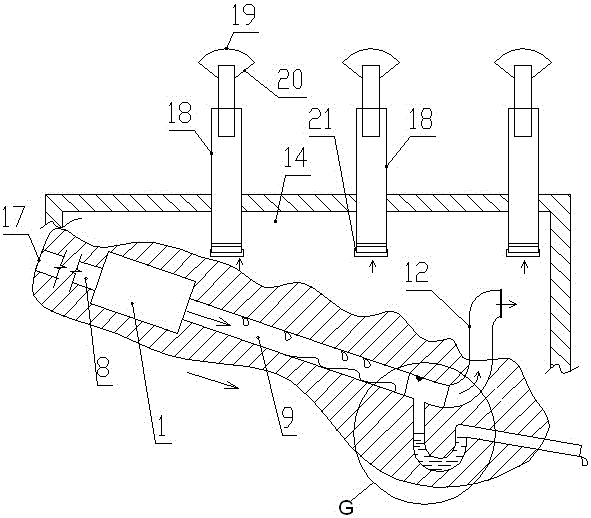
[0039] Figure 6 The part A in the center is the kiln leg, Figure 6 Part B in the middle shows the excavation place of the foundation pit, Figure 6 Part C in the center shows the cave chamber of the raw earth cave dwelling of the pit kiln. Figure 6 D in the center shows the outline of the pit kiln. Figure 6 Middle E shows the pit kiln Tianxin, Figure 6 Middle F shows the top of the pit kiln.

[0040] figure 1 The direction indicated by the middle arrow is the airflow direction at this place.

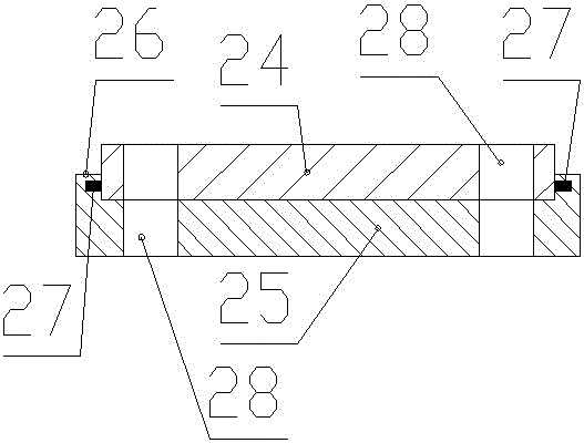
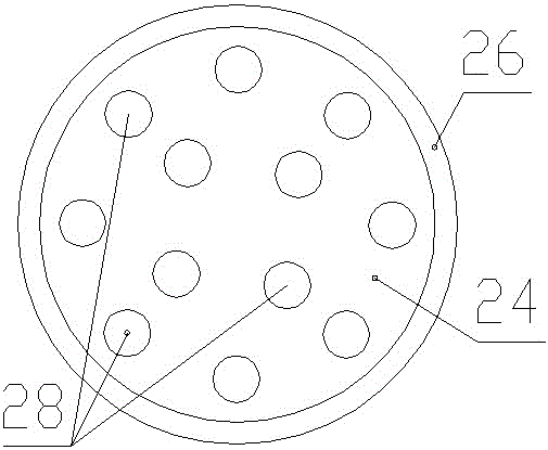
[0041] Such as Figure 1 to Figure 8As shown, the passive ventilation and dehumidification system of the soil source-based raw soil cave dwelling of the present invention includes a new air duct arranged obliquely along the kiln legs of the cave dwelling. The fresh air duct is embedded in the soil and its slope is less than or equal to 20%; the fresh air duct is connected in series There is a soil source heat exchange device 1 .

[0042] The soil source heat exchange device ...


PUM


Abstract

The invention discloses a passive ventilation-dehumidification system of a soil-source-based immature soil cave dwelling. The passive ventilation-dehumidification system comprises fresh air pipes, wherein the fresh air pipes are obliquely arranged along the cave dwelling legs of the cave dwelling and buried in the soil; the slope of each fresh air pipe is lower than or equal to 20%; a soil source heat exchange device is connected in series with the fresh air pipes; three rows of the fresh air pipes are arranged side by side; the bottoms of all the fresh air pipes communicate with one another through a transverse connecting pipe; a U-shaped condensate water pipe and an air supply device are connected with the transverse connecting pipe; air pull-out devices are arranged on the top wall of a cave dwelling chamber; and air volume adjusting devices are arranged at the bottoms of the air pull-out devices. The invention further discloses a construction method of the above passive ventilation-dehumidification system. When the passive ventilation-dehumidification system disclosed by the invention is utilized for cooling or heating inside the cave dwelling, no energy and refrigerant are needed, and no environmental pollution is caused; meanwhile, the freshness of air inside the cave dwelling can be improved, thereby preventing air-conditioning diseases caused by the indoor cycle mode of a conventional air conditioner; and after construction, the existing appearance integrity and the original nature of the conventional cave dwelling can be prevented from being broken.

Description

technical field [0001] The invention relates to the technical field of air conditioning, in particular to a temperature and humidity regulating structure for raw earth cave dwellings. Background technique [0002] Traditional raw earth cave dwellings have the architectural characteristics of being warm in winter and cool in summer, and are natural ecological residences. However, due to poor indoor ventilation, indoor mildew and condensation often occur, seriously affecting the living quality of cave dwellings. [0003] There are two known ventilation improvement technologies for traditional raw earth cave dwellings: 1) One is to use a split air conditioner, whose working principle is that the compressor sucks in low-pressure gaseous refrigerant, which is compressed into high-temperature and high-pressure gas; The gaseous refrigerant flows to the outdoor condenser, and gradually condenses into a high-temperature and high-pressure liquid during the process of heat dissipation...

Claims


Application Information

Patent Timeline
IPC IPC(8): F24F5/00F24F7/06F24F11/00
CPCF24F5/005F24F7/065F24F11/77Y02B10/40Y02B30/70
Inventor 杨晓林吕红医李建东唐丽刘哲
Owner ZHENGZHOU UNIV
Learn More