Back support form support structure for large-aperture reflector

A large-diameter reflector and support structure technology, which is applied in the direction of instruments, installation, optics, etc., can solve problems such as the inability to realize lens array installation, affect the quality and energy of the transmitted beam, and the thick structure of large-diameter reflectors, etc., to achieve a simple structure , high reliability and smooth movement

Pending Publication Date: 2017-05-17
GENERAL ENG RES INST CHINA ACAD OF ENG PHYSICS
View PDF3 Cites 2 Cited by
  • Summary
  • Abstract
  • Description
  • Claims
  • Application Information

AI Technical Summary

Problems solved by technology

The structure of the large-aperture mirror is heavy, expensive, and requires precise positional accuracy, so its positioning adjustment structure must be precise and reliable, with high stability
[0003] Traditional large-diameter reflectors mostly adopt the support method of circumferential clamping. Rubber gaskets or copper sheets are set between the lens and the metal frame to avoid hard contact and compensate part of the mirror deformation. In this structure, the lens can obtain a rigid The disadvantage of edge protection is that the support structure is large in size, and it is difficult to install the lens in a tight position in the radial direction, and the array installation of the lens cannot be realized. Moreover, the surface shape of the center area of ​​the lens placed obliquely changes greatly, which affects the quality and quality of the transmitted beam. energy

Method used


Image

  • Back support form support structure for large-aperture reflector
  • Back support form support structure for large-aperture reflector
  • Back support form support structure for large-aperture reflector

Examples


Embodiment Construction

[0032] The present invention will be further described below in conjunction with accompanying drawing:

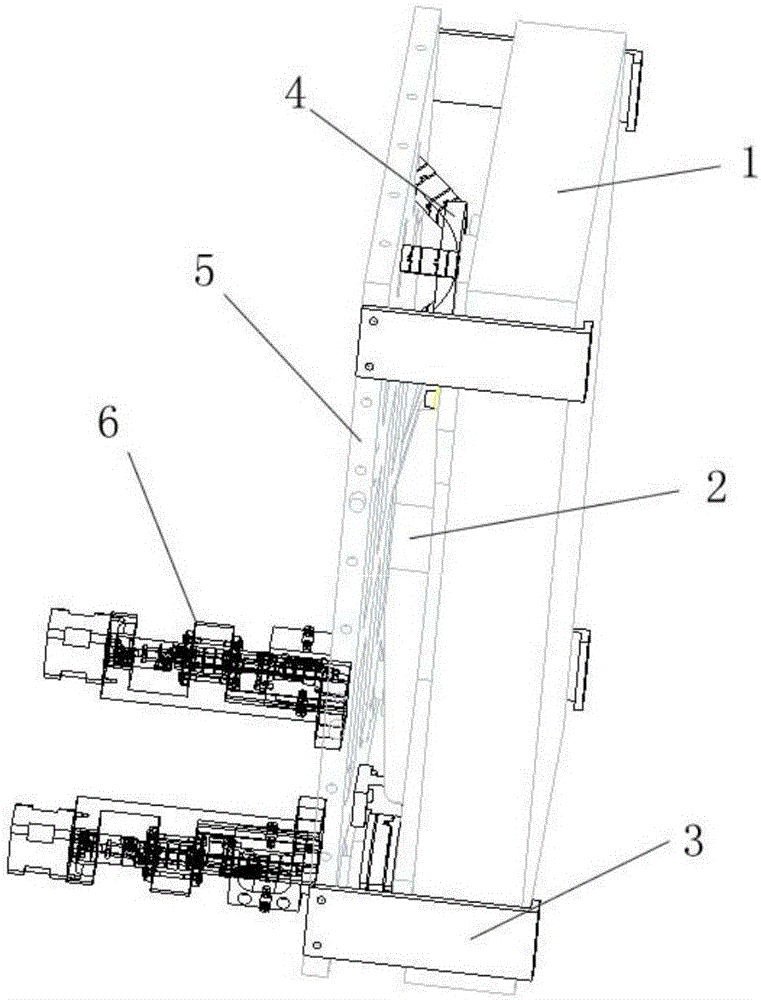
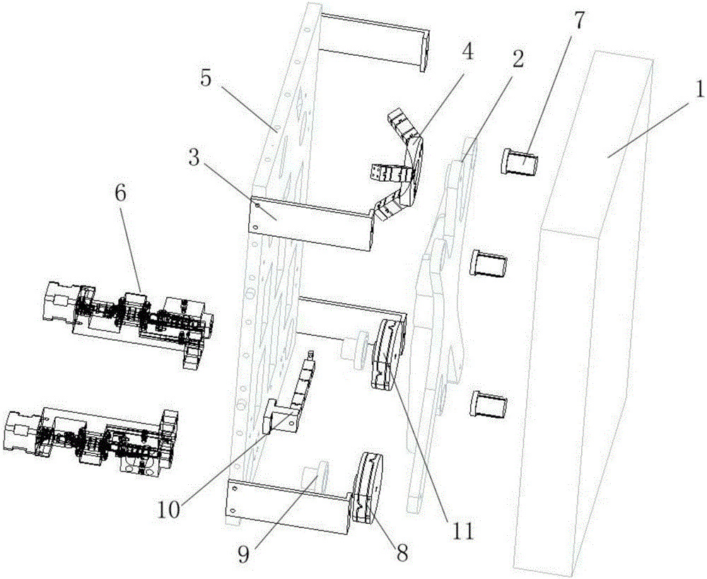
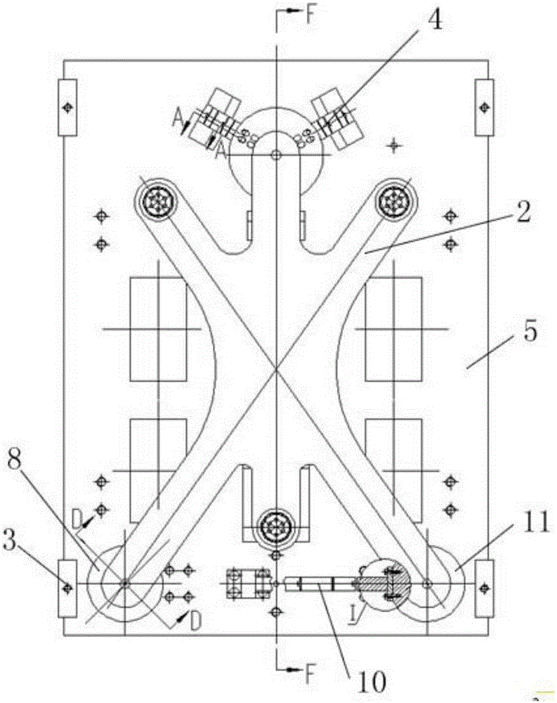
[0033] combine figure 1 , figure 2 , image 3 , Figure 4 , Figure 5 , Image 6 , Figure 7 , Figure 8 , Figure 9 , Figure 10 and Figure 11 As shown, the present invention includes an optical lens 1, ribs 2 and a back plate 5 parallel to each other, a three-claw flexible hinge 4, a disc flexible hinge I8 and a disc flexible hinge II11 are arranged between the ribs 2 and the back plate 5, and the rear The plate 5 is equipped with an anti-rotation flexible hinge 10, four protective sheets 3 and two driving components 6, and the optical lens 1 can be placed at any angle with the ground.

[0034] There are three blind holes on the back of the optical lens 1, and the positions of the blind holes are calculated by mechanics. A precision expansion sleeve 7 is respectively installed in the three blind holes, and the three precision expansion sleeves 7 are fixedly co...


PUM


Abstract

The invention discloses a back support form support structure for a large-aperture reflector. The back support form support structure comprises an optical lens, a rib plate and a back plate, wherein the rib plate is parallel with the back plate, a three-claw flexible hinge, a disc flexible hinge I and a disc flexible hinge II are arranged between the rib plate and the back plate, and the back plate is provided with an anti-rotation flexible hinge, four protecting pieces and two drive components; three blind holes with precise expansion bushings are formed in the back of the optical lens, and the three precise expansion bushings are fixedly connected with the rib plate; the front portion of the three-claw flexible hinge is connected with the rib plate, and the rear portion of the three-claw flexible hinge is connected with the back plate; one ends of disc flexible hinge I and the disc flexible hinge II are in one-to-one correspondence to the two drive components and are connected through a connector, the other end of the disc flexible hinge I and the other end of the disc flexible hinge II are connected with the rib plate, and the anti-rotation flexible hinge is connected to the lateral side of the disc flexible hinge II; the four protecting pieces are connected to the back plate through lifting bolts, and the optical lens is located among the four protecting pieces. The back support form support structure is simple, stable in motion, free of friction, free of gaps, high in motion sensitivity and high in reliability and does not need lubrication.

Description

technical field [0001] The invention belongs to the field of precision optomechanics, and in particular relates to a support structure for a large-diameter reflector in the form of a back support. Background technique [0002] There are a large number of large-aperture mirrors in large scientific installations, and the mirror structure needs to meet the requirements of compact installation space. The relatively spacious space on the back of the mirror should be fully utilized in the mirror support structure. At the same time, the support structure should meet the strict mirror deformation requirements of the mirror to ensure the quality and energy of the reflected beam. The structure of the large-aperture mirror is heavy, expensive, and requires precise positional accuracy, so its positioning adjustment structure must be precise and reliable, with high stability. [0003] Traditional large-diameter reflectors mostly adopt the support method of circumferential clamping. Rubb...

Claims


Application Information

Patent Timeline
Patent Type & Authority Applications(China)
IPC IPC(8): G02B7/183G02B7/198G02B7/182
CPCG02B7/1821G02B7/183G02B7/198
Inventor 陈晓娟吴文凯汪宝旭朱明智苏瑞峰傅学龙
Owner GENERAL ENG RES INST CHINA ACAD OF ENG PHYSICS
Why Eureka
Try Eureka