Display panel driving method and driving device

A driving method and display panel technology, applied in static indicators, instruments, nonlinear optics, etc., can solve the problems of low aperture ratio, high cost, complex structure, etc., reduce aperture ratio, overcome flicker phenomenon, and have wide application prospects Effect

Inactive Publication Date: 2019-11-05
BOE TECH GRP CO LTD
View PDF4 Cites 0 Cited by
  • Summary
  • Abstract
  • Description
  • Claims
  • Application Information

AI Technical Summary

Problems solved by technology

[0005] Embodiments of the present invention provide a driving method and a driving device for a display panel to solve the problems of complex structure, low aperture ratio and high cost in the prior art

Method used


Image

  • Display panel driving method and driving device
  • Display panel driving method and driving device
  • Display panel driving method and driving device

Examples


no. 1 example

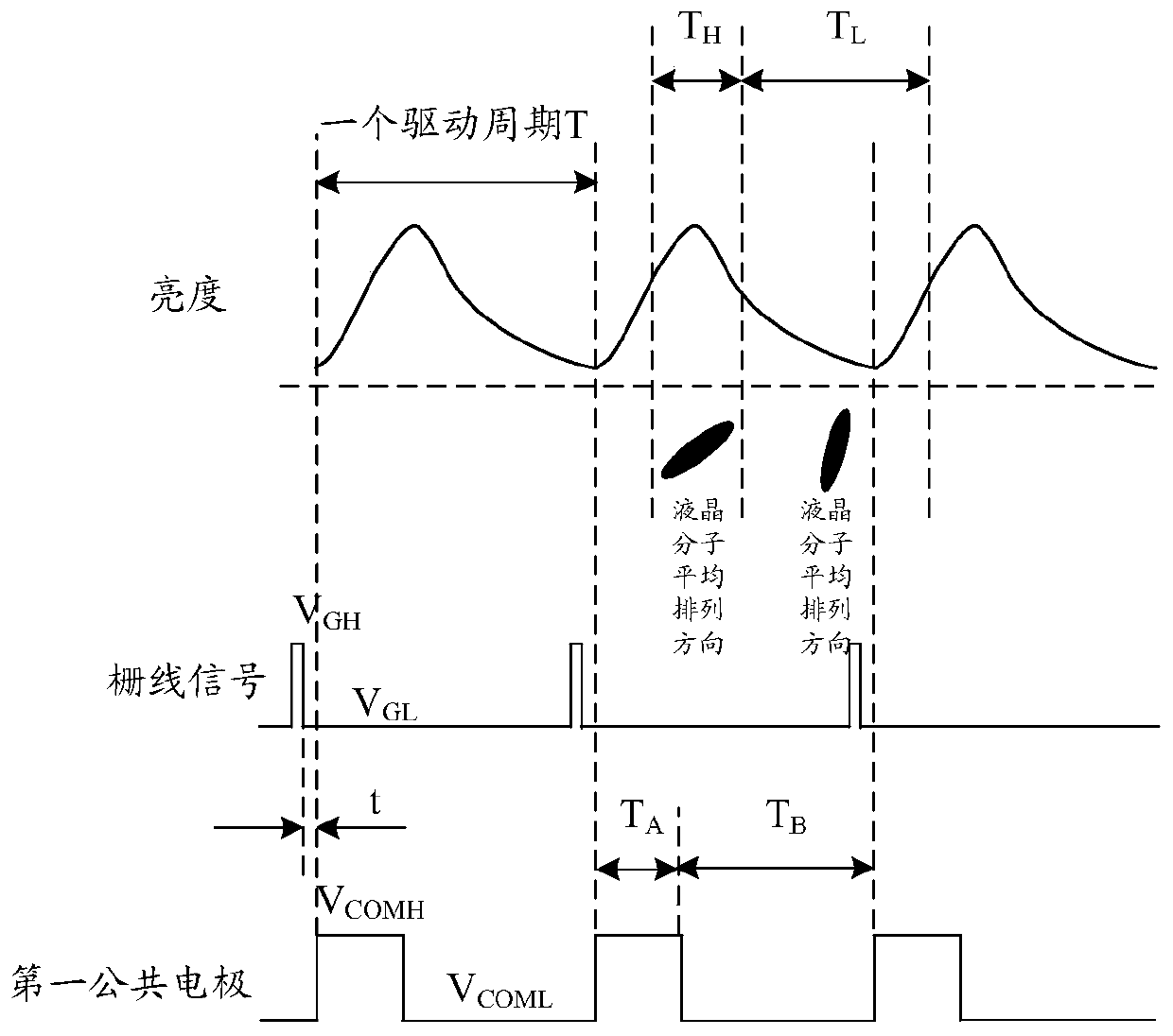
[0044] In this embodiment, a driving cycle is divided into two periods: the first period and the second period. The common voltage applied to the first common electrode is a modulation mode, and a high voltage as the first common voltage is applied in the first period. A flat common voltage, and a low-level common voltage as a second common voltage is applied during the second period. figure 2 It is a schematic diagram of the first embodiment of the driving method of the display panel of the present invention, the duration of the first period T A with the duration of the second period T B The sum is one driving period, and the duration of the second period is greater than the duration of the first period. Preferably, T A with T B The ratio is 1:1.5~1:3.

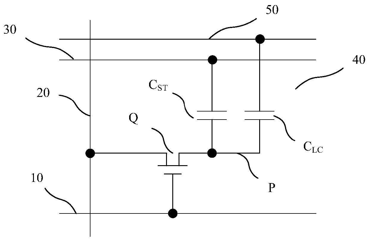
[0045] Such as figure 2 As shown, in the driving method of the display panel in this embodiment, the gate line is passed through the scanning signal (high potential scanning voltage) V GH , the thin film transistor Q ...

no. 2 example

[0053] This embodiment is an extension based on the first embodiment. The difference from the first embodiment is that in this embodiment, a driving cycle is divided into 2 sub-cycles, and each sub-cycle is divided into 2 periods: the first period and In the second period, the common voltage applied to the first common electrode is in modulation mode. image 3 It is a schematic diagram of the second embodiment of the driving method of the display panel of the present invention, the duration of the first period T A with the duration of the second period T B The sum is 1 / 2 of the driving cycle, and the duration of the second period is greater than the duration of the first period. Preferably, T A with T B The ratio is 1:1.5~1:3.

[0054] Such as image 3 As shown, in the driving method of the display panel in this embodiment, after the gate line is turned off, in the first sub-period, the first common electrode is applied with a high-level common voltage V COMH , and the d...

no. 3 example

[0059] In the foregoing first and second embodiments, the high-level common voltage is applied after the gate line is closed, that is, the rising edge of the high-level common voltage of the first common electrode is after the falling edge of the gate line close signal, and the There is a time difference t between them. The characteristic of the driving mode of the aforementioned embodiment is that after the charging of the pixel electrode is completed, the voltage change on the pixel electrode is induced by the coupling effect of the storage capacitor through the common voltage of the modulation mode. The difference from the first embodiment is that in this embodiment, the high-level common voltage as the first common voltage is applied before the gate line is turned on, that is, the rising edge of the high-level common voltage is at the same time as the rise of the gate line turn-on signal. Before the edge, there is a time difference t between the two. The driving mode of t...


PUM


Abstract

Embodiments of the present invention provide a driving method and a driving device for a display panel. The driving method includes: dividing a driving cycle into N sub-cycles, each sub-cycle is divided into a first period and a second period, N is a positive integer greater than or equal to 1; in the first period, the first common The electrodes are loaded with a first common voltage, and during the second period, the first common electrode is loaded with a second common voltage, and the time of the second period is longer than the time of the first period. In the present invention, by applying the common voltage of the modulation mode on the first common electrode, the average arrangement direction of the liquid crystal molecules in the pixel unit changes within one driving cycle, and the brightness of the pixel unit changes, forming domain-doubled display and frequency-doubled display effects , effectively improved the color shift phenomenon, overcome the flicker phenomenon, and significantly improved the multi-domain display effect.

Description

technical field [0001] The present invention relates to the field of display technology, in particular to a driving method and a driving device of a display panel. Background technique [0002] At present, Thin Film Transistor-Liquid Crystal Display (TFT-LCD) can be divided into Twisted Nematic (TN) mode, In Plane Switching (In Plane Switching, IPS) mode, advanced ultra-dimensional Field Switch (Advanced Super Dimension Switch, ADS) mode, Vertical Alignment (Vertical Alignment, VA) mode, etc. Among them, the VA mode in the wide viewing angle display technology has a larger viewing angle performance than the TN mode, and also has excellent Response time and high contrast are widely used in liquid crystal display panels with wide viewing angles. [0003] The display panel in VA mode includes multiple pixel units, and each pixel unit corresponds to a smallest independently controllable display point on the display screen. Under the action of the driving voltage, the liquid cry...

Claims


Application Information

Patent Timeline
Patent Type & Authority Patents(China)
IPC IPC(8): G02F1/133
CPCG02F1/13306G09G3/3607G09G3/3655G09G2300/0447G09G2300/0465G09G2320/0242G02F1/136286G02F2201/121G02F2201/123G02F1/1368
Inventor 严允晟刘立伟方正贾玉娥
Owner BOE TECH GRP CO LTD
Why Eureka
Try Eureka