
Experimental device of manual pressure source for testing multiple fluid pressure volume temperature relationship

A technology of experimental device and measuring device, applied in the direction of measuring device, teaching model, instrument, etc., can solve the problems of high labor cost, valve opening or closing, inability to carry out, etc., to achieve high experimental efficiency, reduced usage, and convenient use. Effect

Inactive Publication Date: 2017-05-17
WUHAN POLYTECHNIC UNIVERSITY
View PDF14 Cites 4 Cited by
  • Summary
  • Abstract
  • Description
  • Claims
  • Application Information

AI Technical Summary

Problems solved by technology

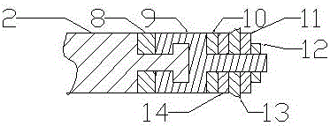
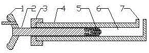
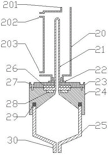
[0003] The determination of the relationship between the pressure, volume and temperature of the fluid and the observation of critical phenomena is an experimental project set up by many universities. Chinese patent CN202599882U discloses the composition of the experimental platform for measuring the critical point of carbon dioxide and the p-v-T relationship. The measurement experimental platform mainly includes an experimental platform Body, constant temperature circulating bath, constant temperature circulating water jacket, piston pressure source, carbon dioxide, etc., but the pressure gauge calibrator is used as the pressure source in the equipment, and castor oil is used as the working fluid. When the temperature is low, due to the castor oil If the viscosity is too high, when the piston is used to pump oil, air will often leak into the oil cylinder from the piston seal, that is, the working fluid cylinder, resulting in the castor oil being unable to be pumped into the oil cylinder, unable to pressurize, and the experiment cannot be carried out. , replace castor oil with transformer oil, the viscosity of transformer oil is small, basically there will be no leakage into the air, but when a high pressure is applied, the transformer oil is easy to leak from the piston seal, so castor oil or transformer oil are used There are defects; in addition, the more serious problem of using the pressure gauge calibrator as a pressure source is: the pressure gauge calibrator has multiple valves, and when the experiment is carried out, the error of valve opening or closing often occurs, Due to the high pressure of the carbon dioxide in the test bench body, the pressure of the oil cup in the pressure gauge calibrator is normal pressure, and the pressure difference between the inside and outside is large, which causes the carbon dioxide in the test body to rush out of the body, causing the equipment to be scrapped, because it is injected into the body of the experimental device It takes skill to fill the fluid. You have to ask the equipment manufacturer to fill the fluid again. The travel expenses and labor costs are very high, and it is also very troublesome. The manufacturer is often unwilling to fill the fluid. When the internal and external pressure difference is small, the pressure gauge will be damaged. This kind of problem often occurs due to improper operation, so the manufacturer is unwilling to produce this kind of equipment, because it is difficult to distinguish the responsibility, and the later maintenance cost is very high; because the volume of the oil cylinder of the pressure gauge calibrator is much smaller than the volume of the oil cylinder in the test bench body, It is necessary to use the piston of the pressure gauge calibrator to pump the oil from the oil cup into the oil cylinder of the main body many times, and the experiment efficiency is low; another disadvantage is that the amount of mercury used as the sealing liquid is large, and often one kilogram of mercury is needed for an experimental device. The hidden dangers are self-evident

Method used


Image

  • Experimental device of manual pressure source for testing multiple fluid pressure volume temperature relationship
  • Experimental device of manual pressure source for testing multiple fluid pressure volume temperature relationship
  • Experimental device of manual pressure source for testing multiple fluid pressure volume temperature relationship

Examples


Embodiment Construction

[0031] In order to further understand and illustrate the application of the invention, the relevant content in the manual pressure generator and the measuring device in the application of the invention will be further explained, and the implementation method of the invention will be described.

[0032]Because the bracket for fixing the manual pressure generator and the measuring device, the fixed structure of the manual pressure generator and the measuring device belong to the known, as the manual pressure generator and the measuring device use hexagonal steel to make, or use round steel bar or steel pipe to make the manual pressure generator The outside of the measuring device is processed into a hexagonal shape, or the surface of the manual pressure generator and the measuring device is welded for fixing and installing parts, so the structure and components of the fixing device are not shown in the figure.

[0033] Vacuum valve, inflation valve, pressure gauge and the connect...


PUM


Abstract

An experimental device of manual pressure source for testing multiple fluid pressure volume temperature relationship comprises a manual pressure generator and a measuring apparatus, the mercury working fluid and sealing liquid. The lower an upper ends of the measuring apparatus are conical, the middle part of the apparatus is cylindrical. The measuring apparatus comprises glass flange capillary, constant temperature circulating water jacket, a sealing liquid container lid, a seal liquid container, a seal, a constant temperature circulating water jacket fixed structure, a vacuum valve, a charging valve, a pressure gauge and a bolt and other accessories, the measuring apparatus is conveniently filling with high purity fluid which comprises carbon dioxide, hexafluoride, ethane, freon 13, freon 23, the manual pressure generator is connected with the measuring apparatus by pressure metal pipe and sleeve joint. The device has the advantages of completely solving the hidden troubles of air leakage, oil leakage and operation errors caused by hydraulic oil not using of a pressure gauge validator ,testing multiple fluid property and being convenient to use.

Description

technical field [0001] The invention relates to an experimental device for measuring and observing fluid properties, in particular to an experimental device for measuring the relationship between pressure, volume and temperature of various fluids and observing critical phenomena, belonging to experimental teaching instruments. Background technique [0002] The property relationship between the pressure (P), volume (V) and temperature (T) of the fluid is the basic property of the fluid and the basic data for calculating the thermodynamic properties of the fluid. With these property data, the fluid can be calculated according to the thermodynamic relationship. Other thermodynamic properties, these properties play an important role in chemistry, chemical industry, refrigeration, heat energy utilization, etc.; the physical data of fluids, such as the critical temperature, critical pressure, critical volume and other properties of fluids, determine the liquefaction, vaporization, ...

Claims


Application Information

Patent Timeline
Patent Type & Authority Applications(China)
IPC IPC(8): G09B23/12G01D21/02
CPCG09B23/12G01D21/02
Inventor 郑立辉程四清翟爱霞
Owner WUHAN POLYTECHNIC UNIVERSITY
Learn More