Resonant wireless power transfer device

A resonant radio and transmission device technology, applied in the direction of circuit devices, electrical components, etc., can solve the problems of inability to take into account the transmission efficiency and transmission distance, and achieve the effects of good coupling, improved transmission efficiency, and high transmission efficiency

Active Publication Date: 2019-01-22
ZHONGBEI UNIV
View PDF3 Cites 0 Cited by
  • Summary
  • Abstract
  • Description
  • Claims
  • Application Information

AI Technical Summary

Problems solved by technology

[0003] In order to solve the problem that the existing wireless power transmission device cannot take into account both transmission efficiency and transmission distance, the present invention provides a resonant wireless power transmission device

Method used


Image

  • Resonant wireless power transfer device
  • Resonant wireless power transfer device
  • Resonant wireless power transfer device

Examples


Embodiment Construction

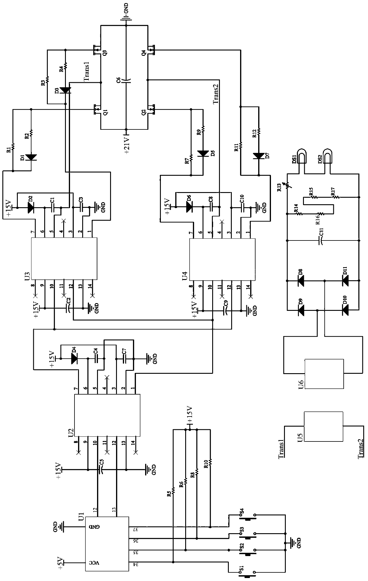
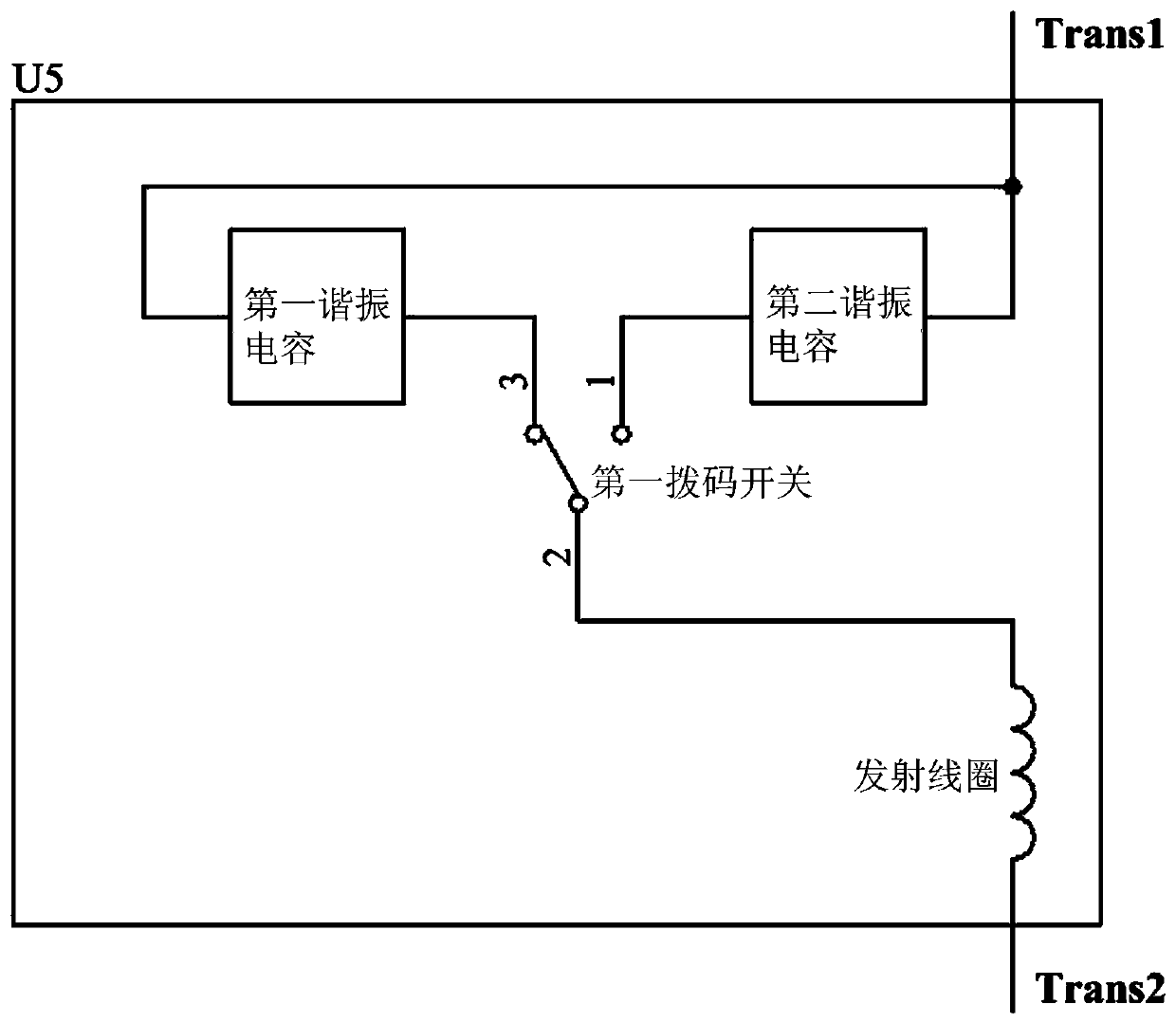
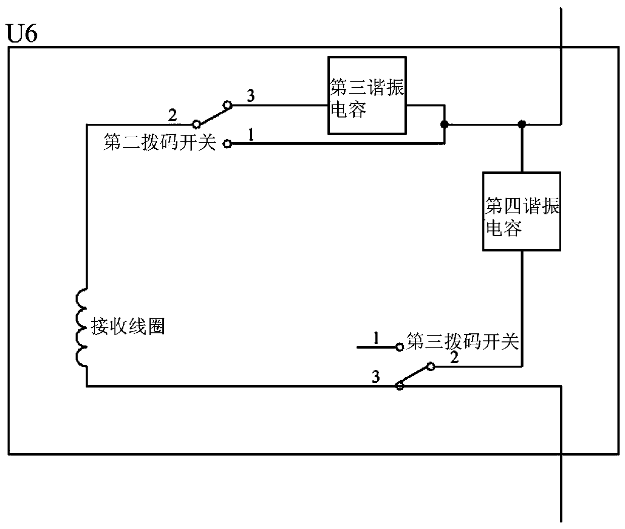
[0022] Resonant wireless power transmission device, including MSP430F149 microcontroller U1, first IR2110 driver chip U2, second IR2110 driver chip U3, third IR2110 driver chip U4, transmitting module U5, receiving module U6, first to fourth MOS transistors Q1~ Q4, first to eleventh diodes D1~D11, first to fourth keyboard switches S1~S4, first bulb DS1, second bulb DS2, first to seventeenth resistors R1~R17, first to fourth The eleventh capacitor C1~C11;

[0023] Among them, the thirteenth resistor R13 is a sliding rheostat; the fourteenth to seventeenth resistors R14~R17 are all power resistors; the second capacitor C2, the fifth capacitor C5, the sixth capacitor C6, the ninth capacitor C9, and the eleventh capacitor Capacitor C11 is an electrolytic capacitor;

[0024] The VCC pin of MSP430F149 MCU U1 is connected to the +5V power supply terminal; the ground pin of MSP430F149 MCU U1 is grounded; the thirty-fourth pin of MSP430F149 MCU U1 is connected to the +15V power supply...


PUM


Abstract

The invention relates to a wireless power transmission device and more particularly relates to a resonance type wireless power transmission device. By virtue of the resonance type wireless power transmission device, the problem of no consideration for both transmission efficiency and transmission distance in the existing wireless power transmission device is solved. The resonance type wireless power transmission device comprises an MSP430F149 single chip microcomputer, a first IR2110 driving chip, a second IR2110 driving chip, a third IR2110 driving chip, a transmitting module, a receiving module, first to fourth MOS tubes, first to eleventh diodes, first to fourth keyboard switches, a first bulb, a second bulb, first to seventh resistors and first to eleventh capacitors, wherein the transmitting module comprises a transmitting coil, a first resonance capacitor, a second resonance capacitor and a first dial switch; the receiving module comprises a receiving coil, a third resonance capacitor, a fourth resonance capacitor, a second dial switch and a third dial switch. The resonance type wireless power transmission device is applicable to wireless power transmission.

Description

technical field [0001] The invention relates to a wireless power transmission device, in particular to a resonant wireless power transmission device. Background technique [0002] Currently, wireless power transmission devices mainly include three types: the first type is a wireless power transmission device based on electromagnetic coupling. This kind of device uses the principle of mutual coupling of common magnetic coils for wireless energy transmission. Its advantage is high transmission efficiency, but its problem is that the transmission distance is short (centimeter level). The second is a wireless power transfer device based on radio waves. This kind of device uses the principle of far-field antenna to transmit and receive wireless energy. Its advantage is that the transmission distance is long (kilometer level), but its problem is that the transmission efficiency is low. The third is a wireless power transmission device based on electromagnetic resonance. This de...

Claims


Application Information

Patent Timeline
Patent Type & Authority Patents(China)
IPC IPC(8): H02J50/12
CPCH02J5/005
Inventor 李继伟孟青刘万荣张曼靖程一峰
Owner ZHONGBEI UNIV
Why Eureka
Try Eureka