
Auxiliary device for spinal joint load position medical imaging examination

An auxiliary device and medical imaging technology, applied in medical science, patient positioning for diagnosis, and equipment for radiological diagnosis, etc., can solve the problems that cannot truly reflect physiological and pathological changes

Pending Publication Date: 2017-05-24
SOUTHERN MEDICAL UNIVERSITY
View PDF11 Cites 6 Cited by
  • Summary
  • Abstract
  • Description
  • Claims
  • Application Information

AI Technical Summary

Problems solved by technology

Imaging examinations in the supine position often cannot truly reflect the physiological and pathological changes in the daily activities of the human body

Method used


Image

  • Auxiliary device for spinal joint load position medical imaging examination
  • Auxiliary device for spinal joint load position medical imaging examination

Examples


Embodiment 1

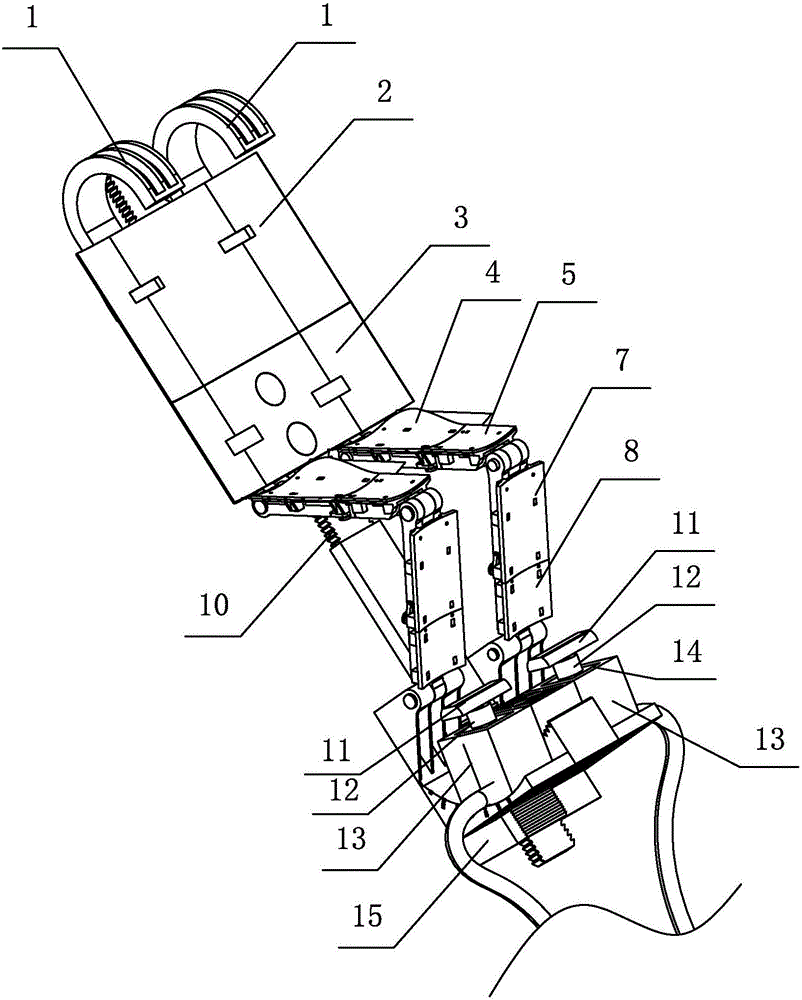
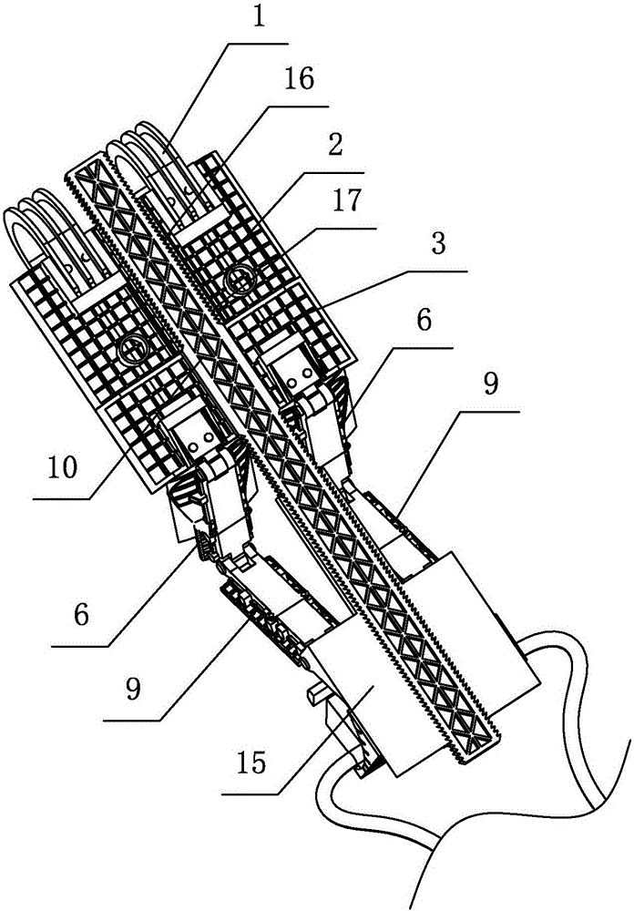
[0033] like figure 1 , figure 2 As shown, an auxiliary device for spinal joint weight-bearing position medical imaging examination of the present invention includes a shoulder force-bearing device, a trunk support plate, a thigh support plate, a calf support plate and a foot force-bearing device connected in sequence, and the trunk support plate , The thigh support and the calf support can play a role in supporting the human trunk, thigh and calf. The shoulder force device is fixedly connected to one end of the trunk support, and one end of the thigh support is hinged to the other end of the trunk support. , the other end of the thigh support plate is hinged to one end of the calf support plate, and the other end of the calf support plate is hinged to the foot force device. The corresponding joints of the hip, knee, and ankle joints of the lower limbs can also be adjusted to different flexion angles, and the joints There are scale marks for easy control and adjustment of the...

Embodiment 2

[0038] An auxiliary device for medical image examination in the weight-bearing position of spinal joints, the other structures are the same as in Embodiment 1, the difference is that: figure 1 , figure 2 As shown, there are two shoulder handles 1, and the two shoulder handles 1 are symmetrically arranged on both sides of the center line of the trunk supporting plate.

[0039] like figure 1 As shown, there are two thigh support plates, and the two thigh support plates are symmetrically arranged on both sides of the center line of the trunk support plate; corresponding to the thigh support plates, there are two calf support plates.

Embodiment 3

[0041] An auxiliary device for medical image examination in the weight-bearing position of spinal joints, the other structures are the same as those in Embodiment 1 or 2, except that: figure 1 , figure 2 As shown, the torso supporting board is arranged as an upper torso supporting board 2 and a lower torso supporting board 3 along the length direction of the human body, the upper torso supporting board 2 is slidably connected to the stretching connecting rod 10, and the lower torso supporting board 3 is fixedly connected to the stretching connecting rod 10. The bottom surface of the upper trunk supporting plate 2 is provided with a groove 17, and the inner edges of the groove 17 are serrated teeth 16, which are compatible with the tension connecting rod 10; the bottom surface of the resistance base plate 15 is provided with a groove 17, and the groove 17 The inner edges of both sides are serrated teeth 16, which are compatible with the tension connecting rod 10; 17 inlaid, ad...


PUM


Abstract

The invention relates to the technical field of medical appliances, and particularly relates to an auxiliary device for spinal joint load position medical imaging examination. The auxiliary device comprises a should stress device, a body supporting plate, a thigh supporting plate, a shank supporting plate and a foot stress device which are connected sequentially, wherein the shoulder stress device is fixedly connected to one end of the body supporting plate; one end of the thigh supporting plate is hinged at the other end of the body supporting plate, and the other end of the thigh supporting plate is hinged at one end of the shank supporting plate; the other end of the shank supporting plate is hinged on the foot stress device; a stretch connecting rod is arranged between the body supporting plate and the foot stress device; and one end of the stretch connecting rod is fixedly connected with the body supporting plate, and the other end of the stretch connecting rod is connected with the foot stress device in a sliding manner. The shoulder stress device and the foot stress device are used as supporting, when feet constantly pedal downwards at full tilt, the shoulder stress device and the foot stress device form counter-acting forces, and the load state of the spine and lower limb joints of a body is simulated.

Description

technical field [0001] The invention relates to the technical field of medical devices, in particular to an auxiliary device for medical image examination in a weight-bearing position of a spinal joint. Background technique [0002] The incidence of spine and joint diseases is high, which has a great impact on people's work and life. Clinical diagnosis and curative effect evaluation often require the help of computed tomography (CT) or magnetic resonance (MR) examination. [0003] At present, regardless of whether CT or MR examinations are used clinically, the examinee needs to adopt a supine position, which is very different from the normal postures of daily production and life of the human body. The standing weight-bearing position and the lying position will be different in terms of muscle tension, bone alignment characteristics, and positional relationship of joint structures. Imaging examinations in the supine position often cannot truly reflect the physiological and p...

Claims


Application Information

Patent Timeline
IPC IPC(8): A61B6/04A61B6/03A61B5/055
CPCA61B6/032A61B6/04A61B6/505A61B5/055
Inventor 李绍林陈焱君张晓东赵银霞
Owner SOUTHERN MEDICAL UNIVERSITY
Learn More